
Installation & Assembly
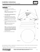

Installation Instructions A470
Otto Small Sphere Pendant Track Version 161305T Page 6 of 8
Modern American Blacksmiths | Fine, Hand Crafted Lighting
Castleton, Vermont USA | HUBBARDTONFORGE.COM 36888
Troubleshooting Guide: 12 Volt Pendant Lighting
Part 1. For Hubbardton Forge Track Lighting products that use the “Fast Jack Male Coaxial Fixture
Connector” from Edge Lighting, an Edge Lighting Installation Instruction “FJ-MC-_” is provided to the
customer. This Instruction shows one method for installing coaxial cable into the coaxial fixture
connector. The method shown omits a trimming step to the Braided Outer Shield, to simplify the
installation.
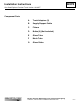
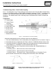
Components:
A. Coaxial Cable
B. Coaxial Fixture
Connector
C. Conical Nipple
D. Strain Relief Tube
E. M4 Set Screw
F. M3 Set Screw
G. Inner Conductor
H. Wire Insulation
I. Braided Outer Shield
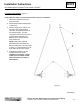
It has been determined that more consistent results can be obtained if:
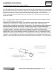
1. The outer braided shield (I) of the coaxial cable (A) is stripped back 3/4" as shown in Figure 1.
2. The M3 Set Screw (F) is tightened until “Tight”, when the 1.5MM Allen Wrench starts to flex.
3. The M4 Set Screw (E) is tightened inward until it no longer causes an interference with the
Conical Nipple (C). It will begin to crush the Strain Relief Tube (D).
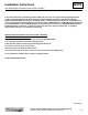
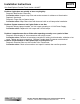
4. 3 Electrical Continuity tests are performed after assembly with a Digital Multi-Meter or
Continuity Tester.
– Continuity Test #1 – Short Circuit test, tester should not light.
– Continuity Test #2 – Open Circuit test, tester should light.
– Continuity Test #3 – Functional Check. Same probe positions as Continuity Test #1,
performed with Fixture wired and a working bulb in the socket, tester should light.
Figure 1 - Coaxial Cable and Connector Assembled
Figure 2 - Continuity Test #1
Figure 3 - Continuity Test #2