SuperStor Contender Solar Supplement INSTALLATION OPERATION MAINTENANCE TROUBLESHOOTING SB Series* Models SSC-50SB / SSC-80SB SSC-119SB SE Series** Models SSC-50SE / SSC-80SE SSC-119SE *With back-up heat exchanger **With back-up electric element The solar energy system described in this manual, when properly installed and maintained, meets the minimum standards established by the SRCC. This certification does not imply endorsement or warranty of this product by the SRCC.
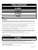
The following defined terms are used throughout this manual to bring attention to the presence of hazards of various risk levels, or to important product information. DANGER indicates an imminently hazardous situation which, if not avoided, will result in death or serious injury. WARNING indicates a potentially hazardous situation which, if not avoided, could result in death or serious injury.
Solar Water Heating System Design and Installation Guidelines, SRCC OG-300, available from Solar Rating & Certification Corporation, 400 High Point Drive, Suite 400, Cocoa, FL 32926-6630, www.solar-rating.org. Code for the Installation of Heat Producing Appliances (latest version), from American Insurance Association, 85 John Street, New York, NY 11038. The latest version of the National Electrical Code, NFPA No. 70. In Canada, refer to Canadian Electrical Code C 22.
L. WIND STRESS.......................................................................................................................................................................... 11 M. SNOW LOAD ........................................................................................................................................................................... 12 N. HAIL RESISTANCE ...................................................................................................................
PART 11 - SYSTEM PARTS LISTING....................................................................................................................................... 30 A. ESTIMATED COMPONENT LIFE ............................................................................................................................................. 30 B. WARRANTIES AND DISCLAIMERS ........................................................................................................................................
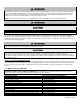
DO NOT USE THIS SOLAR WATER HEATING SYSTEM IF ANY PART HAS BEEN SUBMERGED IN WATER. Immediately call a qualified service technician. Components MUST BE replaced if submerged. Attempting to operate a solar water heating system that has been even partially submerged could create numerous harmful conditions, such as a potential gas leakage causing a fire and/or explosion, or the release of mold, bacteria, or other harmful particulates into the air.
D. INSULATION BLANKETS For installation of insulation blankets, refer to Solar Water Heating System Design and Installation Guidelines, SRCC OG-300. E. DOMESTIC HOT WATER TEMPERATURE ADJUSTMENT An ASSE 1017 rated mixing valve to avoid severe burns or death from scalding temperature IS REQUIRED PER SRCC OG-300. Households with small children, disabled, or elderly persons may require a o 120 F or lower temperature setting to prevent severe personal injury or death due to scalding.
Return – The plumbing line running from the tank (or heat exchanger) to the inlet of the collector. This line incorporates the circulation pump. D. SYSTEM DESIGN PRESSURIZED CLOSED LOOP SYSTEMS A closed loop system uses non-potable HTF and must be pressurized to less than 72.5 psi. Closed loop systems require an expansion tank to accommodate HTF expansion.
Pressurized Closed Loop Systems – These systems use a glycol/water mix as HTF, which protects the system from freezing. These systems operate at high pressures. In systems using a glycol/water mix, freeze protection fluid must be non-toxic propylene glycol, FDA rated as GRAS. To protect the heat exchanger and other system components, regular scheduled maintenance must be established to monitor and maintain proper HTF pH levels.
D. COLLECTOR ANGLE, PLANE, AND DIRECTION 1. COLLECTOR DIRECTION The collector should face the equator. In the northern hemisphere, this is due south, and in the southern hemisphere, due north. Facing the collector in the correct direction and angle is important to ensure o optimal heat output. A deviation of up to 15 from due south is acceptable, and will have minimal effect on heat output. 2.
F. COLLECTOR LOOP PIPE INSULATION The collector loop supply and return lines must be well insulated with high quality, flexible, closed cell insulation to minimize heat loss. Wall thickness of pipe insulation should not be less than ¾". 1" wall thickness is required in all areas prone to annual hard freeze conditions. When it comes to pipe insulation the rule is simple: thicker is better. The specified insulation material is HT/Armaflex or equivalent.
M. SNOW LOAD o In areas prone to heavy snowfall, the solar collector(s) should ideally be installed at an angle of 50 or greater to help promote snow sliding off the collectors. In addition, it is advisable to raise the lower collector frame off the roof surface 6 – 8 inches or higher. Doing this places the collector above moderate snowfall accumulation and allows drifting snow to more easily slide out from under the collector, which helps ensure that snow does not cover the collector array.
PART 4 – SPECIFICATIONS Figure 3 – SB Series Water Heater Dimensions and Specifications LP-200 REV. 3.25.
Figure 4 – SE Series Water Heater Dimensions and Specifications LP-200 REV. 3.25.
PART 5 - INSTALLATION A.
Wire Stripper or Knife Wire Cutters Adjustable Wrenches 8” & 10” Solder Flux Aluminum Flashing Sheet Black Latex Outdoor Paint 7/8” x ¾” and 1 1/8” x ¾” pipe insulation Emory Paper B. SOLAR WATER HEATER LOCATION To minimize expense and heat loss, locate the solar water heater as centrally to the domestic piping system and near the solar collectors as possible. The water heater must also be located in an area where it will not be exposed to freezing temperatures.
heater and marked Hot and Cold. It is recommended that unions or flexible copper connectors be used so heater can be easily serviced. Install a shut-off valve on the cold feed near the solar water heater to isolate the tank for future service. Provide clear access to the storage tank, pump, expansion tank, mixing valve, time clock and other key components.
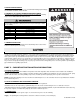
Water with a high TDS concentration will greatly accelerate lime and scale formation in the hot water system. Most high TDS concentrations precipitate out of the water when heated. This can generate a scale accumulation that will greatly reduce the service life of a water heater. The manufacturer of the water heater has no control over water quality, especially TDS levels in your system.
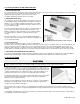
D. SOLAR HEAT EXCHANGER PIPING Set up the primary balance of the system components following the piping detail in Figure 6. Run ½” type M or larger copper pipes, or flex line sets, to and from the collector following the direction of supports, penetrations, and other relative items. Only copper, cast iron, or brass are to be allowed in the collector piping loop due to transient operating temperatures that may reach as o high as 300 F.
Expansion Tank Pre-charged with air to allow for the expansion and contraction of HTF. Drain Valve (Valve #10) Used to charge the collector loop with glycol, purge air from the loop and drain the solar water heater heat exchanger of fluid. Collector Isolation Valve (for system fill) (Valve #11) Used to direct the flow of HTF and to pressurize and eliminate air from the solar system. Ball Valve (for circulator) Valve #12 Used to isolate the circulator pump for service.
It is very important that you do the potable piping before you pipe into the solar system. Failure to do so may damage your water heater. Improper installation IS NOT covered by warranty. Dielectric unions or galvanized steel fittings must be used on the domestic water connections or auxiliary connections. Teflon thread sealant must be used on all connections. Failure to do so could result in premature water heater failure. Such failure IS NOT covered by warranty. LP-200 REV. 3.25.
G. SOLAR WATER HEATER WITH BOILER BACK-UP Figure 7 – Solar Water Heater with Boiler Back-up – FIGURE NOTES: 1. This drawing is meant to show system piping concept only. The installer is responsible for all equipment and detailing by local codes. 2. Antifreeze, non-potable HTF shall be used for the solar heat exchanger circuit only. Never introduce antifreeze solution to any connection other than the solar loop. 3.
H. SOLAR WATER HEATER WITH ELECTRIC BACK-UP Figure 8 – Solar Water Heater with Electric Back-up FIGURE NOTES: 1. This drawing is meant to show system piping concept only. The installer is responsible for all equipment and detailing by local codes. 2. Antifreeze, non-potable HTF shall be used for the solar heat exchanger circuit only. Never introduce antifreeze solution to any connection other than the solar loop. 3.
I. BOILER BACK-UP HEAT EXCHANGER CONNECTION (SB MODELS ONLY) The boiler heat exchanger connections are located in the front of the solar water heater. Use a 1” minimum pipe size when connecting zone valves or circulators. The inlet of the circulator must be connected to the hot outlet side of the boiler. Be sure the direction of the arrow on the circulator is facing toward the flow direction from the boiler to the boiler inlet of the water heater.
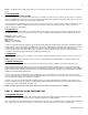
M. ELECTRICAL CONNECTION (SE MODELS ONLY) Tank must be full before unit is turned on. The heating element will be damaged if energized for even a short period of time while tank is dry. This damage IS NOT covered by warranty. Be sure to ground the water heater. The preferred way to ground is with rigid metal conduit between the main panel and the water heater junction box with approved end fittings (check codes on the use of flexible conduit).
N. THERMOSTAT ADJUSTMENT o The thermostat is located in the front of the heater. The access cover must be removed to adjust the factory default setting of 119 F. This temperature is satisfactory for average household use. If an adjustment is necessary, turn off the power to the heater, remove the black access cover and insulation. The thermostat protective cover should not be removed. Set the temperature indicator to the desired temperature, replace insulation and access cover.
NOTE: HTP DOES NOT WARRANT THE SOLAR WATER HEATER, SOLAR COLLECTOR, OR ANY COMPONENTS AGAINST FREEZE RELATED DAMAGE. PART 8 – START-UP PREPARATION DO NOT MOVE ON TO THESE STEPS UNTIL THE ENTIRE SOLAR SYSTEM, INCLUDING ALL PIPING, SOLAR COLLECTORS, SENSORS, PUMP, CONTROLS, AND ELECTRICAL CONNECTIONS, ARE PROPERLY SECURED, INSULATED, LABELED AND INSTALLED. A. CHARGING THE SYSTEM Solar Water Heater Fill the solar tank with water. Do this by opening the cold water isolation ball valve to the solar tank.
performance of the solar water heater and cause overheating of the collector system. You must install a mixing valve on the hot water outlet, as temperature within the storage tank can cause injury. PART 9 – SERVICE/MAINTENANCE PROCEDURES A properly maintained solar water heating system can provide years of dependable, trouble-free service. It is suggested that a routine preventive maintenance program be established and followed by the end user with the solar contractor.
Following installation of the T&P Relief Valve, the valve lever MUST be operated AT LEAST ONCE A YEAR by the water heater owner to ensure that waterways are clear. Certain naturally occurring mineral deposits may adhere to the valve, blocking waterways and rendering the valve inoperative. When the lever is operated, hot water will discharge if the waterways are clear. PRECAUTIONS MUST BE TAKEN TO AVOID PERSONAL INJURY FROM CONTACT WITH HOT WATER AND TO AVOID PROPERTY DAMAGE.
NATURE OF TROUBLE Water too hot or not hot enough Noisy heating element Table 3 POSSIBLE CAUSE 1. Thermostat setting too high or low 2. Thermostat out of calibration 3. Solar system incorrectly installed 4. Grounded element Scale built up on element SERVICE Change setting as required **Replace **Check installation **Replace **Remove and clean See water heater installation manuals for more detailed maintenance information.
Figure 13 – SE Model Parts Breakdown – LP-200-E Item No SSC-50SE SSC-80SE / 119SE 1 6075P-002 6075P-008 2 6075P-003 6075P-009 3 6075P-044 6075P-044 4 6075P-054 6075P-054 5 6075P-052 6075P-052 6 6060P-1008 6060P-1008 7 6060P-633 6060P-633 8 6060P-632 6060P-632 9 6060P-994 6060P-994 10 6060P-187 6060P-187 11 6075P-006 6075P-006 12 N/A N/A 13 6075P-053 6075P-053 14 TP1000 TP1000 15 SN1002 SN1002 16 N/A 6060P-631 Table 5 – SE Model Replacement Parts List Description HOT WATER OUTLET HOT WATER DIP TUBE ANOD
Figure 14 - SB Model Parts Breakdown Item No SSC-50SB SSC-80SB / 119SB 1 6075P-002 6075P-008 2 6075P-003 6075P-009 3 6075P-044 6075P-044 4 6060P-1009 6060P-1009 5 6060P-633 6060P-633 6 6060P-632 6060P-632 7 6060P-952 6060P-952 8 6075P-053 6075P-053 9 6075P-006 6075P-006 10 N/A N/A 11 6060P-187 6060P-187 12 TP1000 TP1000 13 SN1002 SN1002 14 N/A 6060P-631 Table 6 – SB Model Replacement Parts List Description HOT WATER OUTLET HOT WATER DIP TUBE ANODE ROD, STANDARD SOLID THERMOSTAT CONTROL THERMODISC MOUNT
LP-200 REV. 3.25.
LP-200 REV. 3.25.
o o VISCOSITY: The HTF viscosity over the service temperature range is based on a specific gravity 15/15 C (60/60 F) 1.053-1.063. o o o DOWFROST inhibited glycol-based fluid has an effective operating temperature range of -50 F to 250 F. At temperatures below -50 F, increased viscosity (>1,000 centipoise) can make use of DOWFROST impractical unless larger pumps are installed. At the upper end of o the operating range for DOWFROST fluid, a maximum bulk temperature of 250 F is recommended.
SYSTEM MODELS 2007011A 2007011B 2007011C 2007012A 2007012B 2007012C SOLAR COLLECTOR COMPANY HTP HTP HTP HTP HTP HTP MODEL AE-32E AE-40E AE-32E AE-32E AE-40E AE-32E # OF COLLECTORS 1 1 2 1 1 2 Table 7 Part CONTROLLER PUMP EXPANSION TANK CHECK VALVE PRESSURE RELIEF VALVE AIR VENT MIXING VALVE PIPING HEAT TRANSFER FLUID SOLAR SYSTEM REPLACEMENT PARTS Company Model STECA TRO301 GOLDLINE GL-30 HELIOTROPE Thermal Delta T TACO OO7 GRUNDFOS 15-58F AMTROL Extrol #30 WATTS SERIES 600* *(ALTERNATE APPROVED
LP-200 REV. 3.25.
MAINTENANCE NOTES LP-200 REV. 3.25.
HTP CUSTOMER INSTALLATION RECORD FORM The following form should be completed by the installer for you to keep as a record of the installation in case of a warranty claim. After reading the important notes at the bottom of the page, please also sign this document.