Phoenix / Versa-Hydro Solar Supplement INSTALLATION OPERATION MAINTENANCE TROUBLESHOOTING Phoenix Models PH130-80S / 130-119S PH199-80S / 199-119S Versa-Hydro Models PHE130-80S / 130-119S PHE199-119S / 199-119S The solar energy system described in this manual, when properly installed and maintained, meets the minimum standards established by the SRCC. This certification does not imply endorsement or warranty of this product by the SRCC.
The following defined terms are used throughout this manual to bring attention to the presence of hazards of various risk levels, or to important product information. DANGER indicates an imminently hazardous situation which, if not avoided, will result in death or serious injury. WARNING indicates a potentially hazardous situation which, if not avoided, could result in death or serious injury.
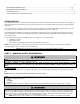
Solar Water Heating System Design and Installation Guidelines, SRCC OG-300, available from Solar Rating & Certification Corporation, 400 High Point Drive, Suite 400, Cocoa, FL 32926-6630, www.solar-rating.org. The latest version of the National Fuel Gas Code, ANSI Z223.1, from American Gas Association Laboratories, 8501 East Pleasant Valley Road, Cleveland, OH 44131. In Canada – CGA No.
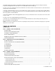
G. COLLECTOR SENSOR PLACEMENT ..................................................................................................................................... 11 H. AVOID SHADE ......................................................................................................................................................................... 11 I. LOCATION ...............................................................................................................................................
A. ESTIMATED COMPONENT LIFE ............................................................................................................................................. 26 B. WARRANTIES AND DISCLAIMERS ........................................................................................................................................ 26 MAINTENANCE NOTES .....................................................................................................................................................
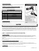
Install all system components and piping in such a way that does not reduce the performance of any fire rated assembly. Failure to do so may lead to fire, property damage, personal injury, or death. Be sure to disconnect electrical power from the solar water heating system before performing service. Failure to do so could result in an electrical shock, property damage, serious personal injury, or death. Improper installation or use may result in property damage. Such damage IS NOT covered by warranty.
D. INSULATION BLANKETS For installation of insulation blankets, refer to Solar Water Heating System Design and Installation Guidelines, SRCC OG-300. E. DOMESTIC HOT WATER TEMPERATURE ADJUSTMENT An ASSE 1017 rated mixing valve to avoid severe burns or death from scalding temperature IS REQUIRED PER SRCC OG-300. Households with small children, disabled, or elderly persons may require o a 120 F or lower temperature setting to prevent severe personal injury or death due to scalding.
Supply – The plumbing line running from the outlet of the collector to the tank (or heat exchanger). Return – The plumbing line running from the tank (or heat exchanger) to the inlet of the collector. This line incorporates the circulation pump. D. SYSTEM DESIGN PRESSURIZED CLOSED LOOP SYSTEMS A closed loop system uses non-potable HTF and must be pressurized to less than 72.5 psi. Closed loop systems require an expansion tank to accommodate HTF expansion.
Pressurized Closed Loop Systems – Closed loop solar systems use a glycol/water mix as HTF, which protects the system from freezing. These systems operate at high pressures. In systems using a glycol/water mix, freeze protection fluid must be non-toxic propylene glycol, FDA rated as GRAS. To protect the heat exchanger and other system components, regular scheduled maintenance must be established to monitor and maintain proper HTF pH levels.
D. COLLECTOR ANGLE, PLANE, AND DIRECTION 1. COLLECTOR DIRECTION The collector should face the equator. In the northern hemisphere, this is due south, and in the southern hemisphere, due north. Facing o the collector in the correct direction and angle is important to ensure optimal heat output. A deviation of up to 15 from due south is acceptable, and will have minimal effect on heat output. 2.
F. COLLECTOR LOOP PIPE INSULATION The collector loop supply and return lines must be well insulated with high quality, flexible, closed cell insulation to minimize heat loss. Wall thickness of pipe insulation should not be less than ¾". 1" wall thickness is required in all areas prone to annual hard freeze conditions. When it comes to pipe insulation the rule is simple: thicker is better. The specified insulation material is HT/Armaflex or equivalent.
M. SNOW LOAD o In areas prone to heavy snowfall, the solar collector(s) should ideally be installed at an angle of 50 or greater to help promote snow sliding off the collectors. In addition, it is advisable to raise the lower collector frame off the roof surface 6 – 8 inches or higher. Doing this places the collector above moderate snowfall accumulation and allows drifting snow to more easily slide out from under the collector, which helps ensure that snow does not cover the collector array.
PART 4 – SPECIFICATIONS Figure 3 – Phoenix Solar Water Heater Dimensions and Specifications LP- 204 REV. 3.25.
Figure 4 – Versa-Hydro Solar Water Heater Dimensions and Specifications PART 5 - INSTALLATION A.
Have water supply tested and ensure it meets the requirements outlined in the Part 2, Section E of this manual Relief Valve Temperature and Pressure relief valve properly installed and discharge line runs to open drain Discharge line not exposed to freezing temperatures Discharge line constructed of copper Wiring Power supply voltage agrees with the water heater rating plate Branch circuit wire fusing or circuit breaker properly sized Electrical connections tight and properly grounded
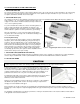
Figure 5 – Clearances Filled hot water storage tanks are very heavy, and should be located in areas that can structurally support such weight. Failure to properly locate water storage tanks could result in property damage, personal injury, or death. PART 6 – PIPING The design and installation of the solar water heating system should be done by qualified individuals. It is important that good design and installation practice be followed to assure that your system will operate properly.
B. GENERAL PIPING DETAIL Figure 6 – This drawing is meant to demonstrate solar system piping only. FIGURE NOTES: 1. This drawing is meant to show system piping concept only. The installer is responsible for all equipment and detailing by local codes. 2. Antifreeze, non-potable HTF shall be used for the solar heat exchanger circuit only. Never introduce antifreeze solution to any connection other than the solar loop. 3.
When making a connection to the heat exchanger, use Teflon Tape and joint compound to prevent leaks. The connections to the heat exchanger are 1” NPT. Do not apply heat directly to the heat exchanger thread connection when sweating fittings. Line pressure and temperature gauge shall be installed in the collector supply and return lines to allow for a simple diagnostic check of o proper system operation.
Ball Valve (for circulator) Valve #12 Used to isolate the circulator pump for service. Close both ball valves to isolate pump. Circulator (#13) Circulates the HTF from the solar collector into the solar heat exchanger. Drain Valve (Tank) (Valve #14) Flushes sediment which may accumulate on the bottom of the solar water heater and also provides a means of draining the tank.
F. SOLAR PIPING WITH AIR HANDLER Figure 7 - This drawing is meant to demonstrate system piping concept only. FIGURE NOTES: 1. This drawing is meant to show system piping concept only. The installer is responsible for all equipment and detailing by local codes. 2. Antifreeze, non-potable HTF shall be used for the solar heat exchanger circuit only. Never introduce antifreeze solution to any connection other than the solar loop. 3.
G. SOLAR PIPING WITH CENTRAL HEATING Figure 8 FIGURE NOTES: 1. Minimum pipe size should match connection size on appliance. If you require greater flow, upsize pipe accordingly. 2. A thermal expansion tank suitable for potable water must be sized and installed within the piping system between the check valve and cold water inlet of the appliance. 3. Gas line must be rated to the maximum capacity of the unit. Unit must have 10 feet of pipe after gas regulator. 4.
H. TANK CONTROL Install the solar sensor onto the threaded stud provided in the front of the water heater (sensor not included). Additional equipment may be needed in order to wire the control to the existing system. Controls also have the ability to monitor and display solar collector temperature and upper and lower tank temperatures. See Figure 10 for installation detail. I.
In order to meet health and safety regulations, solar system antifreeze fluid should be food grade polypropylene glycol, FDA rated as “generally recognized as safe” (GRAS). Using proper concentrations of glycol, solar systems can be operated at ambient temperatures o as low as -60 F. Freeze tolerance limits are based upon an assumed set of environmental conditions. Refer to the DOWFROST specification sheet in the back of this manual for recommended concentrations.
drain valves open, run the low flow diaphragm pump until the HTF begins flowing into the empty bucket. Quickly switch the hose from the empty/return bucket to the bucket containing the glycol mixture. Continue to circulate the fluid using the pressure pump until the bubbling has stopped and the air has been purged. After charging the collector loop, shut the lower drain valve (#10) and let the pressure pump drive up the loop pressure to the appropriate level (in glycol systems, in the range of 25 psi).
The collector loop can be isolated from the solar storage tank by closing (#6 and #11). If the pressure in this loop drops, or you find a glycol leak, shut these valves and contact your installation contractor. Turn the circulating pump off on your solar control. B. VACATION SHUTDOWN Solar water heaters can build up very high temperatures when there is no daily draw on the system.
NATURE OF TROUBLE No hot water Not enough hot water Water too hot or not hot enough Table 3 POSSIBLE CAUSE 1. Improper wiring 2. No power – blown fuse or circuit breaker tripped a. Shorted wiring b. Circuit overloaded c. Improper wiring 3. Solar system incorrectly installed 4. Leaking plumbing or open hot water faucet(s) 1. Heater undersized 2. Wired incorrectly 3. Solar system incorrectly installed 1. Setting too high or low 2. Solar system incorrectly installed SERVICE Rewire per Wiring Diagram a.
LP- 204 REV. 3.25.
LP- 204 REV. 3.25.
o o VISCOSITY: The HTF viscosity over the service temperature range is based on a specific gravity 15/15 C (60/60 F) 1.053-1.063. o o o DOWFROST inhibited glycol-based fluid has an effective operating temperature range of -50 F to 250 F. At temperatures below -50 F, increased viscosity (>1,000 centipoise) can make use of DOWFROST impractical unless larger pumps are installed. At the upper end of o the operating range for DOWFROST fluid, a maximum bulk temperature of 250 F is recommended.
SOLAR COLLECTOR COMPANY HTP HTP SYSTEM MODELS 2007023A 2007023B MODEL # OF COLLECTORS AE-40E AE-32E 1 2 Table 5 Part CONTROLLER PUMP EXPANSION TANK CHECK VALVE PRESSURE RELIEF VALVE AIR VENT MIXING VALVE PIPING HEAT TRANSFER FLUID SOLAR SYSTEM REPLACEMENT PARTS Company Model STECA TRO301 GOLDLINE GL-30 HELIOTROPE Thermal Delta T CALEFFI TACO OO7 GRUNDFOS 15-58F WILO AMTROL Extrol #30 CALEFFI WATTS SERIES 600* *(ALTERNATE APPROVED EQUIVALENT) WATTS 3L (75 psig) CONBRACO TACO 417* *(ALTERNATE A
LP- 204 REV. 3.25.
MAINTENANCE NOTES LP- 204 REV. 3.25.
HTP CUSTOMER INSTALLATION RECORD FORM The following form should be completed by the installer for you to keep as a record of the installation in case of a warranty claim. After reading the important notes at the bottom of the page, please also sign this document.