
Phau Ntawv Qhia
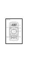


AC VOLTAGE MEASUREMENT
1.
2.
3.
4.
Connect the red test lead to “V.W. mA” jack and the black
test lead to the “COM” jack.
Set the rotary switch at desired ACV position.
Connect test leads across the source or load being
measured.
Read voltage value on the LCD display.
RESISTANCE MEASUREMENT
1.
2.
3.
4.
Connect the red test lead to “V. W. mA” jack and black test
lead to the “COM” jack. (The polarity of red lead is positive
“+”.)
Set the rotary switch at desired ”W” range position.
Connect test leads across the resistor to be measured and
read LCD display.
If the resistance being measured is connected to a circuit,
turn off power and discharge all capacitors before
applying test probes.
DIODE TEST
1.
2.
3.
Connect the red test lead to “V.W.mA” jack and the black
test lead to the “COM” jack (The polarity of red lead is
positive “+”.).
Set the rotary switch at “ ” position.
Connect the red test lead to the anode of the diode to be
tested and the black test lead to the cathode of the diode.
The approx. forward voltage drop of the diode will be
displayed. If the connection is reversed,only figure “1” will
be shown.
TRANSISTOR TEST
1.
2.
3.
Set the rotary switch at “hFE” position.
Determine whether the transistor under testing is NPN or
PNP and locate the emitter,base and collector leads.
Insert the leads into proper holes of the hFE socket on the
front panel.
Read the approximate hFE value at the test condition of
base current 10µA and Vce 3V.
-7-