
Manual

GSC53N - GSC57 - ZG47
EN - 84
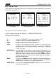
8.4. "VOLTAGE" FUNCTION
This function permits you to display in real time the RMS value of AC/DC voltage, the peak
and Thd value of the 3 phase voltages (see paragraph REF _Ref530398168 \r \h 17.11),
the waveform and the harmonic spectrum of the 3 phase voltages.
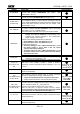
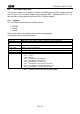
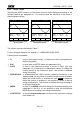
8.4.1. Symbols
The VOLTAGE position has three working modes:
METER
WAVE
HARM
These modes will be described in detail in the next paragraphs.
The symbols used are described below:
Symbol
Description
V1, V2, V3
RMS value of the voltage of phase 1, phase 2, phase 3 respectively
V12, V23 or V32,
V31
RMS Value of the phase to phase voltages
Vpk1, Vpk2, Vpk3,
Vpk12, Vpk32
Peak value of the voltage of phase 1, phase 2, phase 3 and of the phase to phase
voltage 12 and 32 respectively
h01 h49
Harmonic 01 Harmonic 49.
ThdV
Factor of total harmonic distortion of the voltage (see paragraph 17.11).
freq
Network frequency
Phseq
Phase sequence indicator
"123" correct
"132" inverted
"023" null voltage on the black wire
"103" null voltage on the red wire
"120" null voltage on the green wire
"100" null voltages on the red and green wires
"020" null voltages on the black and green wires
"003" null voltages on the black and red wires
Table 7: symbols used in the position VOLTAGE