
Manual

GSC53N - GSC57 - ZG47
EN - 82
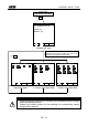
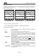
CO-GENERATION
ON = the instrument is able to face situations of CO-GENERATION
of electrical equipment (that is, the equipment under test is
able to generate energy besides absorbing it). Accordingly, the
instrument will record the powers and energies both absorbed
and generated (see paragraph 17.12.1). If this flag is
enabled the maximum number of parameters which can
be selected decrease to 38.
OFF = the instrument will record ONLY the powers and energies
absorbed.
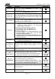
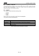
Pt, P1, P2, P3,
P12, P32
Values of the active power (total, of phase 1, phase 2 and phase 3)
(only for 3 wires measurement) value of the power measured by
the Wattmeter 1-2 and 3-2 respectively
Single phase: P1
3 wires: Pt
4 wires Pt, P1, P2, P3
Qti, Q1i, Q2i, Q3i,
Q12i, Q32i
Values of the inductive reactive power (total, of phase 1, phase 2,
phase 3)
(only for 3 wires measurement) value of the reactive inductive
power measured by the VAR meters 1-2 and 3-2 respectively
Single phase: Q1i Q1c
3 wires: Qti Qtc
4 wires Qti Q1i Q2i, Q3i
Qtc Q1c Q2c, Q3c
Qtc, Q1c, Q2c, Q3c,
Q12c, Q32c
Values of the capacitive reactive power (total, of phase 1, phase
2, phase 3)
(only for 3 wires measurement) value of the reactive capacitive
power measured by the VA meters 1-2 and 3-2 respectively
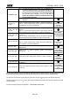
St, S1, S2, S3, S12,
S32
Values of the apparent power (total, of phase 1, phase 2, phase
3)
(only for 3 wires measurement) value of the power measured by
the VA meters 1-2 and 3-2 respectively
Single phase: S1
3 wires: St
4 wires St, S1, S2, S3
Pft, Pf1, Pf2, Pf3
Values of the power factors (total, of phase 1, phase 2 and phase
3 respectively)
Single phase: Pf1 dPf1
3 wires: Pft dPft
4 wires Pft Pf1 Pf2 Pf3
dPft dPf1 dPf2 dPf3
dpft, dpf1, dpf2, dpf3
Values of the cos (total, of phase 1, phase 2 and phase 3
respectively)
Eat, Ea1, Ea2, Ea3
Values of the active energy (total, of phase 1, phase 2, phase 3)
Single phase: Ea1
3 wires: Eat
4 wires Eat Ea1 Ea2 Ea3
Erit, Eri1, Eri2, Eri3
Values of the inductive reactive energy (total, of phase 1, phase 2
and phase 3)
Single phase: Eri1 Erc1
3 wires: Erit Erct
4 wires Erit Eri1 Eri2
Eri3
Erct Erc1 Erc2 Erc3
Erct, Erc1, Erc2, Erc3
Values of the capacitive reactive energy (total, of phase 1, phase
2, phase 3)
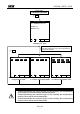
The value of the network frequency is automatically selected if at least one phase voltage (for the single-phase mode or the
4 wires three phase mode) or at least one phase-to-phase voltage (for the 3 wires three phase mode) is selected.
The symbols "i" and "c" stand for reactive powers (Q), power factors (Pf) and cos (dpf) inductive and capacitive respectively.
Selecting a power factor (Pf) or a cos (dPf) for the recording automatically their inductive value and their capacitive value will be
recorded separately.
For eventual messages displayed see Appendix 1 – MESSAGES DISPLAYED