
Manual

GSC53N - GSC57 - ZG47
EN - 81
Symbols
Description
Advised settings
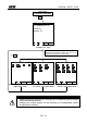
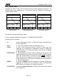
START:MAN
The recording of all the selected parameters will start at 00
seconds after pressing START/STOP (see chapter REF
_Ref6712586 \r \h 10.1).
STOP:MAN
The recording of all the selected parameters will be interrupted
manually by pressing START/STOP (see chapter 10.1).
START:AUTO
STOP:AUTO
The recording of all the selected values will be started / interrupted at
the set dates and times. In order to start the recording the user will
have to press START/STOP to set the instrument in Stand-by mode
until the start date and time previously set (see chapter REF
_Ref6712622 \r \h 10.1).
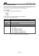
INT. PERIOD
The value of this parameter determines every how many seconds
the values of all the selected parameters will be memorised
(see chapter 17.13.1). Available choices:
5sec,10sec,30sec,1min,2min,5min,10min,15min,30min,60min.
15min
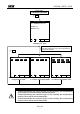
HARM REC.
ON = the instrument will record the values of the selected
voltage and current harmonics corresponding to the
voltages and currents selected in the corresponding
pages “Voltage” and “Current”.
Example: If the following Parameters are selected:
a) Phase Voltage 1 and 2, THd, Harmonics 1,3,5.
b) Phase Current 2 and 3, THd, Harmonics 3,5,7.
The instrument will record:
a) The Phase Voltage 1 and 2, THD and Harmonics 1,3,5 of
the Phase Voltage 1 and 2 while it will not record
anything about Phase Voltage 3
b) The Phase Current 2 and 3, THD and Harmonics 3,5,7 of
the Phase Current 2 and 3 while it will not record nothing
about Phase Current 1
OFF = the instrument will not record any voltage or current harmonic selected
ANOM REC.
ON = the Instrument will record Voltage Anomalies (voltage Sag
and Surge) (see paragraph 17.10)
OFF = the instrument will not record any voltage Sag and Surge
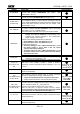
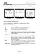
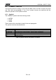
V1, V2, V3
V12, V23 or V32,
V31
RMS value of the voltage of phase 1, phase 2, phase 3
respectively, values of the phase-to-phase voltages 1-2, 2-3 or 3-
2 and 3-1.
Single phase: V1
3 wires V
12
V
32
V
31
4 wires V
1
, V
2
, V
3
THD, DC, 01...49
Voltage Total Harmonic Distortion, DC Component, 01..49
Harmonics respectively
THD,01,03,05,07
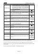
Vref
(only if ANOM. REC flag
has been set ON)
RMS reference value for Voltage used in Voltage Anomalies
detection (Voltage Sag and Surge). The Reference is:
a) Voltage Phase to Neutral for Single Phase and 4 wires three phase system
b) Voltage Phase to Phase for 3 wires three phase system
Single phase: 230V
3 wires: 400V
4 wires 230V
LIM+, LIM-
(only if ANOM. REC flag
has been set ON)
High and Low Voltage Percent threshold used in Voltage
Anomalies detection (Voltage Sag and Surge). These parameters
can be adjusted in range: 3% 30% (step 1%).
Example: Three Phase System 4 wires, Vref = 230V
LIM+= 6%, LIM-=10% => High Lim = 243.8V, Low Lim = 207.0V
The Instrument will detect a voltage Anomalies if the RMS Voltage Values (calculated
every 10ms) beyond the above calculated thresholds (see paragraph 17.10.
Single phase,
3wires, 4wires:
+6% / -10%
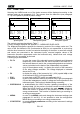
I1, I2, I3, IN
RMS value of the current of phase 1, phase 2, phase 3 and of the
neutral respectively.
Single phase: I1
3 wires: I1, I2, I3
4 wires I1, I2, I3, IN
THD, DC, 01..49
Current Total Harmonic Distortion, DC Component, 01..49
Harmonics respectively
THD,01,03,05,07