
Manual

GSC53N - GSC57 - ZG47
EN - 64
6.6.2. Measurement Procedure and Result of "VDROP" mode
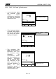
1. Select the "VDROP" mode by means of the F1 key.
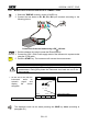
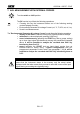
2. Connect the test leads to B1, B2, B3, B4 input terminals according to the
following picture:
B2 B3
B4B1
I1
I2
I3
230V~
50Hz
1.3A
Connection of the test leads during LOW 10A test.
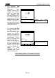
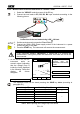
3. Set the conductor area by mean the F3 and F4 keys.
4. Connect the 230V~ 50Hz Power supply socket of the instrument to a power
socket using the C5700 cable.
5. Press the START key. The instrument will execute the measurement..
WARNING
If the instrument displays "Measuring" it means that it is effecting the
measurement. During this phase the instrument test leads are not to be
disconnected.
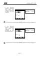
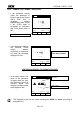
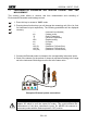
At the end of the test the
instrument emits an
acoustic signal (indicating
that the voltage Drop is
inside the limits displayed
in the following Table) and
display the screen
alongside.
LOW 10A 05.06.01
Voltage Drop across the
conductor under test
referred to a test current
of 10A
1.07V
13.4A 0.107
VDROP SECTION:0.7
Resistance value
Test Current Value
FUNC
Working mode
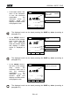
The displayed result can be stored pressing the SAVE key twice (according to
paragraph 9.1).
Area (mm
2
)
Max Voltage Drop (V)
Guidelines
0,5
5
---
0,7
5
1,0
3,3
---
1,5
2,6
2,5
1,9
4,0
1,4
6,0
1,0
Table6: table reporting the Voltage Drop limit values.
START
STOP