
Manual

GSC53N - GSC57 - ZG47
EN - 49
6.4.6. Measurement procedure and results of " " mode
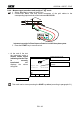
1. Select mode by means of the F1 key.
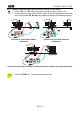
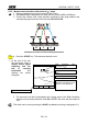
2. Connect the Black, Red and Green connectors of the split cables to the
corresponding input terminals of the instrument B1, B2, B3.
B2 B3
B4
B1
I1
I2 I3
1
3
Instrument connection for Phase Sequence Detection in a 400V three-phase system
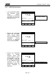
3. Press the START key to execute a test.
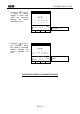
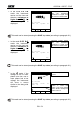
At the end of the test
the instrument emits a
double sound signal
indicating that the test
is correctly
terminated and
displays the values
alongside.
LOOP 05.06.01
Phase Sequence OK
RST
FRQ=50.0HZ VR-S=391V
VS-T=401V VT-R=399V
OK
Value of the Phase to Phase
Voltage
FUNC
Working mode
This result can be stored pressing the SAVE key twice (according to paragraph 9.1).