
Manual

GSC53N - GSC57 - ZG47
EN - 45
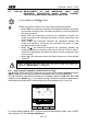
6.4.4. Measurement procedure and results of "P-PE" mode
1. Select P-PE mode by means of the F1 key.
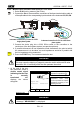
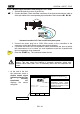
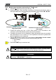
2. Connect the Black, Green and Blue connectors of the three-terminal shuko cable or
of the split cables to the corresponding input terminals of the instrument B1, B3, B4.
P
B2
B3
B4B1
I1
I2
I3
Instrument connection for P-PE test in a 230V
single-phase System
B2 B3
B4
B1
I1
I2 I3
1
3
N
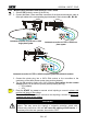
Instrument connection for P-PE in a 400V three-
phase system
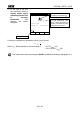
B2 B3
B4
B1
I1
I2 I3
1
3
Instrument connection for P-PE in a 400V three-phase system without Neutral conductor
3. Connect the shuko plug into a 230V 50Hz socket or the crocodiles to the
conductors of the three-phase system (see previous pictures).
4. The key F4 permits to select one of the following limit values for the contact
voltage (which can be shown cyclically when pressing the key):
50V (default).
25V.
5. Press the START key once to execute a test injecting a current in phase with
positive half wave of the voltage.
Press the START key twice to execute a test injecting a current in phase with
negative half wave of the voltage.
WARNING
The P-PE measurement in a 230V System make flow a test current of 6A
approx. This may cause the tripping of magnetic protection switch with
nominal value lower than 10A and will cause the tripping of RCD device. If
necessary effect the test upstream the switch or RCD.
START
STOP