
Manual

GSC53N - GSC57 - ZG47
EN - 41
6.4.2. Measurement procedure and results of "P-N" mode
1. Select P-N mode by means of the F1 key.
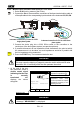
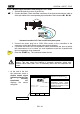
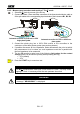
2. Connect the Black, Green and Blue connectors of the three-terminal shuko cable or
of the split cables to the corresponding input terminals of the instrument B1, B3, B4
P
B2
B3
B4B1
I1
I2
I3
Instrument connection for P-N test in a 230V
single-phase System
B2 B3
B4
B1
I1
I2 I3
1
3
N
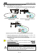
Instrument connection for P-N in a 400V three-
phase system
3. Connect the shuko plug into a 230V 50Hz socket or the crocodiles to the
conductors of the three-phase system (see previous pictures).
4. If possible disconnect all low impedance loads downstream the point at which
the measurement is to be taken, as such impedances would be in parallel with
the line impedance to be measured.
5. Press the START key. The instrument starts the test.
WARNING
The measurement in a 230V System make flow a test current of 6A approx.
This may cause the tripping of magnetic protection switch with nominal value
lower than 10A. If necessary effect the test upstream the switch.
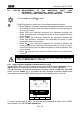
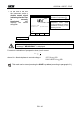
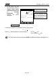
At the end of the test
the instrument emits a
double sound signal
indicating that the test
is correctly
terminated and
displays the values
alongside.
LOOP 05.06.01
Value of phase to neutral line
impedance expressed in .
1.07
215A
FRQ=50.0HZ
VP-N=231V VP-PE=231V
P-N
Value of the phase to neutral
prospective short circuit
current expressed in Ampere
calculated according to the
following formula.
FUNC
Z2
Working mode
WARNING
Never disconnect the test leads from the circuit under test when the
message " MEASURING " is displayed.
START
STOP