
Manual

GSC53N - GSC57 - ZG47
EN - 15
6.1.1. Calibrating the test leads ("CAL" Mode)
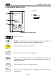
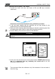
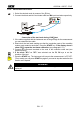
1. Connect the black and blue test leads to B1 and B4 input terminals
respectively.
B2 B3
B4B1
Connection of instrument terminals during calibration procedure.
2. If the test leads supplied with the instrument are not long enough for the
measurement you can extend the blue cable.
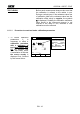
3. Short-circuit the measuring cable ends making sure that the conductive parts of the
crocodiles make a good contact to each other (see previous picture).
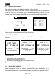
4. Press the F2 key. The instrument carries out the calibration.
WARNING
Never disconnect the test leads when the message "MEASURING" is
displayed.
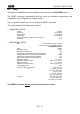
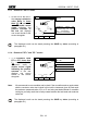
LOW 05.06.01
----
R+ R-
---- ----
---mA ---mA
AUTO 0.11
A numerical value
in this field means
that the instrument
has been
calibrated; this
value remains on
the display for
any further
measurement
even though the
unit is switched off
and on again.
FUNC
CAL
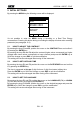
5. At the end of the test the result is stored and used as OFFSET (that is to say
that it is subtracted from any continuity test carried out) for all the
subsequent measurements.
Note: The instrument effects the calibration only if the resistance of the test leads is
lower than 5 .