
Manual

GSC53N - GSC57 - ZG47
EN - 14
6. SAFETY TEST FUNCTIONS
6.1. LOW : CONTINUITY TEST WITH 200mA TEST CURRENT
WARNING
Before carrying out the continuity test make sure that there is no voltage at the
ends of the conductor under test.
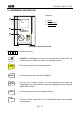
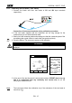
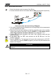
Turn the switch on LOW position.
This key permits to select one of the following measuring modes:
Mode "AUTO" (the instrument carries out two measurements with
reversed polarity and displays their average value). This mode is
recommended for the continuity test.
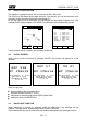
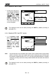
Mode "RT+" (measurement with positive polarity and possibility of setting
the duration time of the test). In this case the operator can set a
measuring time long enough to permit him to move the protective
conductors while the instrument is carrying out the test so detecting any
bad connection.
Mode "RT-" (measurement with negative polarity and possibility of setting
the duration time of the test). In this case the operator can set a
measuring time long enough to permit him to move the protective
conductors while the instrument is carrying out the test so detecting any
bad connection.
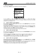
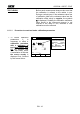
This key permits to execute the "CAL" mode (compensation of the resistance
of the cables used for the measurement).
WARNING
If the resistance is lower than 5 (including the resistance of the calibration)
the continuity test is executed by the instrument with a test current higher than
200mA. If the resistance is higher than 5 the continuity test is executed by the
instrument with a current lower than 200mA.
N.B.
We recommend you to check the Calibration of the test leads before executing a
measurement according to next paragraph.