
Manual

GSC53N - GSC57 - ZG47
EN - 138
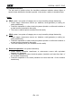
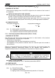
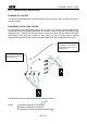
The measuring method allows to define the
specific resistance up to the depth
corresponding approximately to the distance
“a” between the rods. If you increase the
distance “a” you can reach deeper ground
layers and check the ground homogeneity.
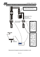
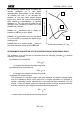
After several measurements, at growing
distances “a”, you can trace a profile like the
following ones, according to which the most
suitable rod is chosen:
Curve1: as decreases only in depth, it’s
possible to use only a rod in depth.
Curve2: as decreases only until the depth
A, it’s not useful to increase the depth of the
rod beyond A.
Curve3: even at a superior depth, does not
decrease, therefore a ring rod must be used.
APPROXIMATE EVALUATION OF THE CONTRIBUTION OF INTENTIONAL RODS
The resistance of a rod Rd can be calculated with the following formulas ( = medium
resistivity of the ground).
a) resistance of a vertical rod
Rd = / L
L= length of the element touching the ground
b) resistance of an horizontal rod
Rd = 2 / L
L= length of the element touching the ground
c) resistance of linked elements
The resistance of a complex system with more elements in parallel is always higher
than the resistance which could result from a simple calculation of elements in
parallel, especially if those elements are close and therefore interactive. For this
reason, in case of a linked system the following formula is quicker and more effective
than the calculation of the single horizontal and vertical elements:
Rd = / 4r
r= radius of the circle which circumscribes the link.
1
2
3
Earth rods distances "a" (m)
Resistivity ( m)