ENGLISH User’s manual ©Copyright HT ITALIA 2005 Release EN 1.
XL423 - XL424 INDEX 1. SAFETY PRECAUTIONS AND PROCEDURES .......................................................................................... 2 1.1 1.2 1.3 1.4 Preliminary instructions ......................................................................................................................................... 2 During use............................................................................................................................................................. 3 After use.
XL423 - XL424 1. SAFETY PRECAUTIONS AND PROCEDURES This meter has been designed in compliance with EN 61010 directive. For your own safety and to avoid damaging the instrument we suggest you follow the procedures hereby prescribed and to read carefully all the notes preceded by the symbol . WARNING Should you fail to keep to the prescribed instructions you could damage the instrument and/or its components or endanger your safety.
XL423 - XL424 1.2 DURING USE Carefully read the herewith recommendations and instructions: WARNING • Non compliance with warnings and/or instructions may cause damage to the tester or its components or injure the operator. • During a measurement never touch any unused terminal. 1.3 AFTER USE If you expect not to use the instrument for a long period of time remove the batteries and strictly follow the indications at paragraph 9.2. 1.
XL423 - XL424 2 GENERAL DESCRIPTION 2.1 INTRODUCTION Dear Customer, the instrument you have just purchased will grant you accurate and reliable measurements provided that it is used according to the present manual’s instructions. The instrument was designed to grant the user the utmost safety conditions thanks to a new concept assuring double insulation and overvoltage CAT III 600V~ between inputs and to ground. 2.2 FUNCTIONS This manual is referred to two models: XL423 and XL423.
XL423 - XL424 3 PREPARATION FOR USE 3.1 PRELIMINARY CHECKS This instrument has been checked mechanically and electrically before shipment. All precautions have been taken to assure that the instrument reaches you in perfect condition. However, it is advisable to carry out a rapid check in order to detect any possible damage, which might have occurred in transit. Check the accessories contained in the packaging to make sure they are the same as reported in chapter 11. 3.
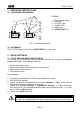
XL423 - XL424 4 OPERATING INSTRUCTIONS 4.1 INSTRUMENT DESCRIPTION LEGEND: L1 L1 L2 L3 1 2 3 4 1. 2. 3. 4. 5. 6. Phase Voltage Inputs COM input “STATUS" LED "ALARM" LED RS232 port "START/STOP" key 5 6 Fig. 1: Instrument description 4.2 KEYBOARD LED “STATUS” blinks every time the START/STOP key is pressed. 5 INITIAL SETTINGS 5.1 DATE, TIME AND MEASURING INTERVAL It’s possible to set measuring interval and date and time by using the management program DATALINK.
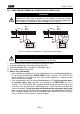
XL423 - XL424 6 MEASURING PROCEDURE 6.1 USING THE INSTRUMENT IN A SINGLE PHASE PLANT WARNING The Instrument can be used in installation with overvoltage CAT III 600V~ between the inputs and to ground. Do not attempt to take any voltage measurements exceeding the limits indicated in this manual. Exceeding the limits could cause electrical shock or damage to the instrument. Nero Black Negro Nero Black Negro Blu Blue Azul Blu Blue Azul Fig.
XL423 - XL424 6. During a Recording: • A STATUS LED 3 seconds blinking meaning that the recording is active and the instrument is storing the data. • An ALARM LED 3 seconds blinking means that the batteries are low. During a recording any RS232 communication is possible. • During Recording operations RS-232 serial communications to PC is not possible. 7. Stop a Recording: • To stop a Recording pressing START/STOP key and keep it pressed for 3 seconds.
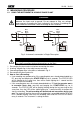
XL423 - XL424 6.2 USING THE INSTRUMENT IN A THREE PHASE 4-WIRES PLANT WARNING The Instrument can be used in installation with overvoltage CAT III 600V~ between the inputs and to ground. Do not attempt to take any voltage measurements exceeding the limits indicated in this manual. Exceeding the limits could cause electrical shock or damage to the instrument. Nero Black Negro Nero Black Negro Blu Blue Azul Blu Blue Azul Rosso Red Rojo Grigio Grey Gris Fig.
XL423 - XL424 6. During a Recording: • A STATUS LED 3 seconds blinking meaning that the recording is active and the instrument is storing the data. • An ALARM LED 3 seconds blinking means that the batteries are low. During a recording any RS232 communication is possible. • During Recording operations RS-232 serial communications to PC is not possible. 7. Stop a Recording: • To stop a Recording pressing START/STOP key and keep it pressed for 3 seconds.
XL423 - XL424 6.3 USING THE INSTRUMENT IN A THREE PHASE 3-WIRES PLANT WARNING The Instrument can be used in installation with overvoltage CAT III 600V~ between the inputs and to ground. Do not attempt to take any voltage measurements exceeding the limits indicated in this manual. Exceeding the limits could cause electrical shock or damage to the instrument.
XL423 - XL424 5. How to start a Recording: • If no recording was performed or if the recording data was already downloaded to a PC, pressing and keeping the START/STOP key for 3 seconds. The STATUS LED will be lighting for the same time, than will be stable lighting for 1 second and the meter will start the recording. • If the recording data was not already downloaded to a PC but the operator wants to overwrite these data, pressing and keeping the START/STOP key for 6 seconds.
XL423 - XL424 7 LED MESSAGES DESCRIPTION For the STATUS and ALARM LEDs messages please refer to the following table: LED START/STOP Key Light STATUS Kept pressed 3 seconds at least On for 1 second STATUS Kept pressed 6 seconds at least 6 times blinking after 1 second on STATUS Not pressed STATUS Not pressed STATUS Pressed ALARM Not relevant 2 times blinking every 3 seconds 1 time blinking every 3 seconds 3 times blinking 1 time blinking every 3 seconds Description Recording process correc
XL423 - XL424 9 MAINTENANCE 9.1 GENERAL INFORMATION This instrument is a precision instrument. Whether in use or in storage, please do not exceed the specifications to avoid any possible damage or danger during use. Do not place this meter in high temperature and/or humidity or expose to direct sunlight. For long term storing, remove the batteries to avoid leakage of battery fluid that can damage the internal components. 9.
XL423 - XL424 10 TECHNICAL SPECIFICATIONS This product conforms to the prescriptions of the European directive on low voltage 73/23/EEC (LVD) and to EMC directive 89/336/EEC, amended by 93/68/EEC. 10.1 CHARACTERISTICS Accuracy is indicated as [% of reading ]. It is referred to: 23°C ± 5°C with RH <60%. VOLTAGE MEASURE Range 0 ÷ 600V Resolution 0.
XL423 - XL424 10.3 ACCESSORIES Description Adhesive Velcro 50 x 70 cm Set of 2 Black/Blue alligator clips (XL423 only) Set of 4 Black/Grey/Red/Blue alligator clips (XL424 only) Carrying bag Management software Serial cable Batteries User’s manual Code VELCRO KITXL423C KITXL424C BORSA2000 DATALINK C2004 GP15AU YAMUM0010HT0 11 SERVICE 11.1 WARRANTY CONDITIONS This equipment is guaranteed against any material fault or manufacturer’s defect, in accordance with the general conditions of sale.