User manual THT70 Copyright HT ITALIA 2014 Release 1.
THT70 Table of contents: 1 PRECAUTIONS AND SAFETY MEASURES ........................................................................... 3 1.1 1.2 2 3 During use ........................................................................................................................................ 3 After use ........................................................................................................................................... 3 GENERAL DESCRIPTION ......................................
THT70 7.4 7.5 7.5.1 7.5.2 8 Accessories provided ....................................................................................................................... 49 Optional accessories ....................................................................................................................... 49 TECHNICAL SPECIFICATIONS ............................................................................................. 50 8.1 8.1.1 9 End of life .............................................
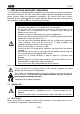
THT70 1 PRECAUTIONS AND SAFETY MEASURES The instrument has been designed in compliance with the directives relevant to electronic measuring instruments. For your safety and in order to prevent damaging the instrument, please carefully follow the procedures described in this manual and read all notes with the utmost attention.
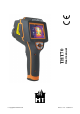
THT70 2 GENERAL DESCRIPTION The instrument is a professional digital thermal camera capable of carrying out infrared temperature measurements of objects and providing high-resolution images in an extremely flexible way. It is also very easy to use and needs little maintenance.
THT70 3 PREPARATION FOR USE 3.1 INITIAL CHECKS Before shipping, the instrument has been checked from an electric as well as mechanical point of view. All possible precautions have been taken so that it is delivered undamaged. However, we recommend generally checking the instrument in order to detect possible damage suffered during transport. In case anomalies are found, immediately contact the forwarding agent. We also recommend checking that the packaging contains all components indicated in § 7.5.
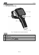
THT70 4 NOMENCLATURE 4.1 INSTRUMENT DESCRIPTION Fig.
THT70 Fig.
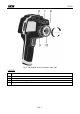
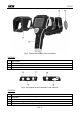
THT70 Fig. 3: General description of the instrument CAPTION: 11 12 13 14 Sun shield Instrument body Universal adapter for tripods Lens protection cap Fig.
THT70 4.2 DESCRIPTION OF FUNCTION KEYS The instrument has 5 function keys indicated as manual and a trigger key “T” with multiple functions. , , , , further in the 4.2.1 Switching on/off the instrument key for approx. 3 seconds to switch on the instrument. After approx. Press and hold the 20 seconds internal autotest, the instrument shows its normal measuring screen. To switch off the instrument, proceed as follows: 1. Press and hold the key for 3 seconds.
THT70 4.2.5 Key Press and hold the “ ” key to switch on the laser pointer which is always active on the instrument. A small red circle “ ” is found in the middle and on the top left-hand side of the display. Releasing the key automatically deactivates the laser pointer. Simply press the “ ” key to activate/deactivate the built-in illuminator with white LED light. The symbol “ ” appears in the top left-hand part of the display. 4.2.
THT70 5 OPERATING INSTRUCTIONS 5.1 DESCRIPTION OF THE MAIN INTERFACE The instrument shows the following main interface on the display: Fig. 6: Main instrument interface The meaning of the symbols found on the display is described below. Symbol Description Active laser pointer (see § 4.2.5) Active built-in illuminator (see § 4.2.5) Manual or automatic calibration activated (see § 4.2.3) Micro SD card inside the instrument Setting of distance from object in VIS-IR screens (see § 5.1.
THT70 5.1.2 Image rotation and zoom The instrument allows performing complete rotations (0 360°) and has a digital electronic zoom function “x1 x20” of the framed IR image. To use these functions, proceed as follows: 1. Touch the symbol “ ” on the display. The instrument shows the following menu at the bottom of the display: Fig. 7: Menu for setting image rotation and zoom 2. Press the “ ” key to activate the zoom function. The indication “0° / 1.
THT70 5.2 MAIN MENU DESCRIPTION Pressing the key or simply touching the display, the instrument shows/hides the following main menu consisting in 6 icons which allow accessing all internal functions: Fig. 9: Main instrument menu Measure menu defines the properties of the tools which can be used for measuring (cursors, lines, areas, object parameters, alarm conditions). Image menu defines the display mode of IR, Visible and Fusion images, the Automatic/Manual modes and the Isotherm line tool.
THT70 Language setting 1. Touch the box “Language”. The following screen appears on the instrument's display: Fig. 11: System language setting 2. Scroll the list of the available languages and touch the desired one. A tick “” is inserted into the corresponding line. 3. Touch “OK” to save your choice and exit the screen or “Cancel” to exit without saving. Setting the Video output Touch the box “Video output”.
THT70 Activation of the built-in illuminator Touch the box “Lamp” to activate (ON) or deactivate (OFF) the built-in illuminator (operation possible also by pressing the key) Adjusting display brightness 1. Touch the box “Brightness”. The following screen appears on the instruments display: Fig. 13: Setting display brightness 2. Scroll the adjusting bar until reaching the desired brightness percentage visible in real time on the display.
THT70 Adjusting the display's switch-off time 1. Touch the box “LCD Off” to activate/deactivate and adjust the display's automatic switch-off time. The following screen appears on the instruments display: Fig. 15: Setting the display's switch-off time 2. Scroll the list of the available values: 1min, 2min, 5min and Off (deactivated option) and touch the desired one. A tick “” is inserted into the corresponding line.
THT70 5.2.1.3 “Images” section In this section it is possible to activate the automatic image saving option with programmable temporal scan. Fig. 17: “Images” section, Setting menu 1. In the box “Repeat”, select the option “ON” to activate the function and touch some internal point of the section. The following screen appears on the instrument's display: Fig. 18: Setting the image saving time 2.
THT70 5.2.1.4 “Date/Time” section In this section it is possible to set the system date/time of the instrument in various formats. Fig. 19: “Date/Time” section, Setting menu 1. Touch the box “Date Format” and select the desired date format considering the options: mm-dd-yyyy, dd-mm-yyyy and yyyy-dd-mm (see Fig. 19). 2. Touch “OK” to save your choice and exit the screen or “Cancel” to exit without saving. 3. Touch the box “24 Hours (ON) / 12 Hours (OFF)”, choosing the desired time format. 4.
THT70 5.2.2 Measure Menu By touching the icon the “Measure” menu is entered, in which it is possible to activate/deactivate and define the characteristics of the measuring tools and temperature analysis. The thermal camera has: Max 3 dynamic measuring cursors Max 2 dynamic horizontal and vertical lines Max 3 dynamic measuring areas 5.2.2.
THT70 Fig. 23: Setting the parameters associated with the cursors 7. Touch the option “Use global parameters” to associate the values of the parameters globally defined on the instrument to the cursor (see §). The symbol “ ” is found on the display and the fields below it are deactivated. 8. With the previous option deactivated (see Fig. 23) it is possible to associate values of parameters “Emissivity”, “Distance” and “Offset” different from the global ones to the cursor.
THT70 5.2.2.2 Setting of Measuring lines In the Measurement menu, by touching the icon “ ” it is possible to activate/deactivate 2 horizontal and vertical lines at the same time, which can be freely positioned onto the image for the description of the temperature profile Fig. 25: Setting of Measuring lines 1. Touch the icon “ ” to activate the desired line. The icon “ ” and the selected line appear on the display (see Fig. 26).
THT70 5. Touch the icon “ ” to set the parameters associated to the lines (see § 5.2.2.5). The following screen appears on the instrument's display: Fig. 28: Setting the parameters associated to the horizontal Line 6. Touch the option “Use global parameters” to associate the values of the parameters globally defined on the instrument to the line (see §). The symbol “ ” is found on the display and the fields below it are deactivated. 7. With the previous option deactivated (see Fig.
THT70 5.2.2.3 Setting of measuring areas In the Measurement menu, by touching the icon “ ” it is possible to activate/deactivate at the same time max 3 areas which can be freely positioned onto the image. The Max, Min and Average values of the internal spots within each selected area may be associated. Fig. 30: Setting of measuring areas 1. Touch the icon “ ” to activate the desired area. The icon “ ” and the activated area appear on the display (see Fig. 31).
THT70 4. Touch the icon “ ” to set the parameters associated to the areas (see § 5.2.2.5). The following screen appears on the instrument's display: Fig. 33: Setting the parameters associated with the areas 5. Touch the option “Use global parameters” to associate the values of the parameters globally defined on the instrument to the area (see §). The symbol “ ” is found on the display and the fields below it are deactivated. 6. With the previous option deactivated (see Fig.
THT70 5.2.2.4 Setting the Measure Menu In the Measure menu, touch the icon “ ” to define: The global settings of the correction parameters of temperature measurement The general settings of the measuring parameters Configuring the alarm conditions on temperature measurement Fig. 35: Setting the Measurement Menu Setting the global parameters 1. Touch the item “Global parameters”. The following screen appears on the instrument's display: Fig. 36: Setting the global parameters 2.
THT70 Fig. 38: Restoring default conditions on the instrument 5. Touch the “Yes” key to restore the default conditions (see Table 1) or the “No” key to cancel the operation. Parameter Default setting Emissivity Distance Environmental temperature Relative humidity Reflected temperature Offset 0.95 5m 25°C 60%RH 25°C 0.0°C Table 1: Thermal camera default settings Setting the general measuring parameters 1. Touch the item “Measure Setting”. The following screen appears on the instrument's display: Fig.
THT70 Setting the alarm on measurement 1. Touch the icon “ display: ” of item “Alarm”. The following screen appears on the instrument's Fig. 40: Setting the alarm conditions on measurement 2. The parameters whose field is included within the symbols “<” and “>” can be set by the user. Target It allows selecting one of the 3 measuring cursors (see § 5.2.2.1) found on the instrument to which to associate the alarm condition on temperature measurement. Possible options: Curs. 1, Curs. 2 or Curs.
THT70 5.2.2.5 Control parameters of temperature measurement The thermal camera allows correcting the measured value of temperature by means of the tools (Spots, Lines and Areas) in the following ways: Global mode the values of the control parameters associated to all tools are defined globally. Custom mode each tool may independently take different values of control parameters according to the selections made by the user.
THT70 Parameters reflected temperature and environmental temperature Objects with a low emissivity may reflect infrared energy coming from adjacent objects; this energy is added to the energy of the object itself, thus causing possible measurement mistakes. In several situations, there are sources of heat with a higher temperature than the temperature found near the object being measured.
THT70 5.2.3 Image menu By touching the icon the “Image” menu is entered, in which it is possible: To set the display type of the IR and visible image on the display Define the colour palettes associated with the IR image Set the temperature level of the image and the image mode Define the characteristics of the Isotherm line tool 5.2.3.
THT70 Fig. 43: Setting and displaying the IR_FUSION_VI image Fig. 44: Setting and displaying the VIS_FUSION_IR image Fig. 45: Setting and displaying the IR_MIX_VIS image Fig. 46: Setting and displaying the VIS_MIX_IR image 1. Touch the symbols “<” and “>” to select the type of desired display. 2.
THT70 5.2.3.2 Setting the colour palette In the Image menu, by touching the icon “ ” it is possible to select the type of colour palette which can be associated to the IR image by choosing between the following options: Standard palette allows choosing between 8 different standard palettes User palette allows the user to define up to 10 custom palettes (2 fixed + 8 which can be fully customized) (this function can be used in Manual mode only – see § 5.2.3.3) Standard palette 1.
THT70 2. The instrument makes two palettes named “Custom1” and “Custom2” which can be freely customized, but cannot be eliminated. These palettes have a default grey colour. 3. Touch one of the two palettes to select them by activating the symbol “ ”. 4. Touch for approximately 2 seconds the line corresponding to the selected palette. The following screen appears on the display: Fig. 49: Customizing the user palette name 5. Touch the item “Rename” to change the name of the palette (max 8 figures).
THT70 8. The screen shows the default palette in uniform grey with division markers in 4 parts in a default temperature range of 0.0°C/F (MIN) 50.0°C/F (MAX) with values of: 12.5, 25.0 and 37.5 9. Touch the MIN 0.0 value and/or the MAX 50.0 value. The following screens are shown on the display: Fig. 52: Customizing the user palette colours – Step 2 10.
THT70 5.2.3.3 Adjusting the image temperature In the Image menu, touch the icon “ ” to set the adjusting mode of the temperature associated with the image framed on the display. The following options are available: Automatic (Auto) mode the minimum and maximum temperature levels of the framed object on the display and associated with the colour palette are automatically defined by the instrument and dynamically vary when moving it.
THT70 Fig. 56: Selection temperature mode CAUTION The screen of Fig. 56 is also shown, as a shortcut, touch the high and low level values located in the palette extremes in the right part of the display 4. Touch the icon “ ” for the setting of the adjustment mode. Touch the symbols “<” and “>” for the selection of Automatic (A), Manual (M) or Histogram (H) modes 5. Touch the icon “ ” or the icon “ ” for the single settings of adjustment respectively of high and low level of temperature.
THT70 5.2.3.4 Setting the Isotherm function In the Image menu, touch the icon “ ” to select the Isotherm function and to activate a screen clearing function. The following options are available (see Fig. 59) Isotherm allows activating the Isotherm function and to define its characteristic. Clear screen allows having the display cleared of all symbols. Fig. 59: Setting the Isotherm tool 1.
THT70 5.2.4 Camera menu In this section it is possible to carry out the following operations: Fixing the images on the display Saving the images on the micro SD card Carrying out voice annotations when saving the image Carrying out text annotations when saving the image 5.2.4.1 Fixing the image on the display and saving An IR image on the display may be saved on the micro SD card inserted in the instrument, after it has been frozen on the display. Proceed as follows: 1.
THT70 5.2.4.2 Voice annotation While saving the image, the instrument allows inserting a vocal comment recorded by the operator (max 60s for each image) as follows: 1. Save the image according to the procedure described in § 5.2.4.1. At the end of the operation, the instrument's situation is shown in Fig. 61 – Left side. Fig. 61: Inserting a voice annotation 2. 3. 4. 5. Touch the icon “ ”. The screen Fig.
THT70 5.2.4.3 Text annotation While saving the image, the instrument allows inserting a text comment entered by the operator (possibly associated with the voice annotation) as follows: 1. Save the image according to the procedure described in § 5.2.4.1. At the end of the operation, the instrument's situation is shown in Fig. 63 – Left side. Fig. 63: Inserting a text annotation 2. Touch the icon “ ”. The screen Fig. 63 – Right side is shown on the display 3.
THT70 5.2.5 Gallery menu In this section it is possible to recall on the display and see the gallery of the IR images saved on the micro SD card inserted in the instrument. In the same section it is possible to see the text annotations and listen to the voice annotations made while saving the images. 1. Touch the icon “ Left side): ” in the main menu. The following screen appears (see Fig. 65 – Fig. 65: Recalling on the display the images saved 2.
THT70 Fig. 66: Display of voice and text annotation 6. Insert the jack of the headphones provided into the instrument (see Fig. 4 – Part 17) and wear the headphones. 7. Touch the icon “ ” to play the voice annotation associated with the image. 8. Touch the icon “ ” to adjust the recording volume. 9. Touch the icon “ ” per stop playing at any time. 10.Touch the icon “ ” to display the text annotation. The screen Fig. 66 – Right side is shown on the display 11.
THT70 5.2.6 Video menu In this section it is possible to recall on the display and see the gallery of the IR videos (MPEG4 format) saved on the micro SD card inserted in the instrument. 1. Touch the icon “ Left side): ” in the main menu. The following screen appears (see Fig. 68 – Fig. 68: Recalling saved IR videos on the display 2. The saved IR videos are shown in reduced dimensions within the gallery.
THT70 5.3 USING THE INSTRUMENT For a typical use of the instrument, please refer to the following procedure: 1. Switch on the instrument by pressing and holding the “ ” key for 3 seconds. After approx. 20 seconds of internal autotest, the instrument shows its normal measuring screen. The instrument shows an initial screen like the one shown in Fig. 70. Fig. 70: Initial screen 2. It takes approx. 30 seconds for the instrument to become fully operating.
THT70 The representation of the ratio D (distance from the object) / S (surface of the object) for an instrument provided with 22mm lens is described below. Fig. 72: Representation of the instruments D/S ratio In the representation, it is possible to see how the IFOV (Instant Field Of View = geometrical resolution of the instrument = size of the single pxl of the IR sensor) is equal to 1.14mm at a distance of 1m of the instrument from the object being measured.
THT70 5.4 TRANSFERRING IR IMAGES/VIDEOS ONTO THE PC The instrument allows saving the IR images/videos on an external micro SD card and to transfer them onto the PC by using the USB cable. Both the micro SD card and the cable are provided with the instrument. Proceed as follows: 1. Insert the micro SD card into the instrument on one side (see Fig. 4 – Part 19). 2. Connect the USB cable to the instrument (see Fig.
THT70 6 USING THE THTLINK SOFTWARE The software “THTLink” can be used to analyse the images saved on the micro SD card inserted in the instrument. 6.1 MINIMUM SYSTEM REQUIREMENTS Hardware: Pentium IV RAM memory: 512MB Output interface: USB ports or SD card reader CD-ROM reader: present Screen resolution: 800x600 Operating system: Windows XP o higher Software applications: Microsoft .Net Framework 2.0 or higher 6.2 INSTALLING THE THTLINK SOFTWARE 1.
THT70 7 MAINTENANCE 7.1 GENERAL INFORMATION 1. The instrument you purchased is a precision instrument. While using and storing the instrument, carefully observe the recommendations listed in this manual in order to prevent possible damage or danger during use. 2. Do not use the instrument in environments with high humidity levels or high temperatures. Do not expose to direct sunlight. 3. Always switch off the instrument after use.
THT70 7.2.2 Recharging by connection to the recharging base 1. Connect the provided battery charger to the AC mains and the recharging base. The green “Power” LED on the base turns on. 2. Insert the battery into the recharging base provided, paying attention to the insertion direction and blocking the battery with the relevant selector. The red “Charge” LED on the base turns on. 3. Carry on the recharging process until the “Charge” LED turns off. 4.
THT70 8 TECHNICAL SPECIFICATIONS Range Sensitivity Accuracy (*) Resolution Image frequency -20°C 400°C <0.06°C@30°C 2%reading or 2°C 384x288pxl 50Hz (*) With standard lens.
THT70 9 SERVICE 9.1 WARRANTY CONDITIONS This instrument is warranted against any material or manufacturing defect, in compliance with the general sales conditions. During the warranty period, defective parts may be replaced. However, the manufacturer reserves the right to repair or replace the product. Should the instrument be returned to the After-sales Service or to a Dealer, transport will be at the Customers charge. However, shipment will be agreed in advance.
NOTE ________________________________________________________________________ ________________________________________________________________________ ________________________________________________________________________ ________________________________________________________________________ ________________________________________________________________________ ________________________________________________________________________ _______________________________________________________________
Via della Boaria, 40 48018 – Faenza (RA)- Italy Tel: +39-0546-621002 (4 linee r.a.) Fax: +39-0546-621144 Email: ht@htitalia.it http://www.ht-instruments.