ENGLISH User manual Copyright HT ITALIA 2013 Release EN 2.
T2000-T2100 Table of contents: 1. PRECAUTIONS AND SAFETY MEASURES ................................................................ 2 1.1. 1.2. 1.3. 1.4. 2. GENERAL DESCRIPTION ............................................................................................ 4 2.1. 2.2. 3. Measuring average values and TRMS values .....................................................................4 Definition of true root mean square value and crest factor ..................................................
T2000-T2100 1. PRECAUTIONS AND SAFETY MEASURES This manual refers to two models: T2000 and T2100. Further in this manual, the word “instrument” will be used to generically refer to both models unless otherwise specified. The instrument has been designed in compliance with directive IEC/EN61010-1 relevant to electronic measuring instruments.
T2000-T2100 1.2. DURING USE Please carefully read the following recommendations and instructions: CAUTION Failure to comply with the Caution notes and/or Instructions may damage the instrument and/or its components or be a source of danger for the operator. Operate the clamp lever twice before switching on the instrument, to make sure that the clamp jaws are completely closed. When switching on the instrument, DO NOT operate the clamp lever and do not clamp any cable.
T2000-T2100 2.
T2000-T2100 3. PREPARATION FOR USE 3.1. INITIAL CHECKS Before shipping, the instrument has been checked from an electric as well as mechanical point of view. All possible precautions have been taken so that the instrument is delivered undamaged. However, we recommend rapidly checking it to detect any damage possibly suffered during transport. In case anomalies are found, immediately contact the dealer We also recommend checking that the packaging contains all components indicated in the § 6.
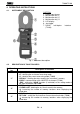
T2000-T2100 4. OPERATING INSTRUCTIONS 4.1. INSTRUMENT DESCRIPTION CAPTION: 1. Double input clamp 2. Multifunction key “1” 3. Multifunction key “2” 4. Multifunction key “3” 5. LCD display 6. Jaw trigger 7. RS232 half-duplex (T2100) interface Fig. 1: Instrument description 4.2.
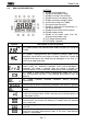
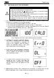
T2000-T2100 4.3. DISPLAY DESCRIPTION CAPTION: 1. Symbol of activated alarm 2. Symbol of low battery charge 3. Symbol of saving in the memory 4. Symbol of access to memory area 5. Display of memory location number 6. Current measuring unit (T2000) 7. Resistance measuring unit 8. Symbol of presence of interferences in the measured circuit 9. Symbol of active Data HOLD function 10.Symbol of open clamp 11.Symbol of resistance lower than the minimum measurable value 12.LCD display decimal points 13.
T2000-T2100 4.4. SWITCHING ON/OFF THE INSTRUMENT CAUTION When switching on the instrument, do not operate the clamp lever, do not open the clamp and do not clamp any cable. When the message “OL. ” appears on the display, it is possible to open the clamp and clamp a cable being measured. Open and close the jaws twice before switching on the instrument in order to check that the clamp properly closes.
T2000-T2100 4.5. RESISTANCE MEASUREMENT CAUTION Measurements carried out by the instrument can be used to evaluate single rods’ resistance values within an earth installation without disconnecting the rods, assuming they do not affect each other. 4.5.1. Operating principle The principle upon which the test carried out by the instrument is based is the “resistive loop resistance measurement”, as shown in Fig. 6: Measurement of loop resistance . Fig.
T2000-T2100 4.5.2. Clamp operation check 1. Press and hold the multifunction key “1” for more than 2 seconds to switch on the instrument. 2. The displayed message “OL ” indicates that the instrument is ready to carry out measurements 3. Open the jaws (the display will show the screen in Fig. 7) and clamp the test loop provided as accessory (see Fig. 8). Fig. 7 Fig. 8: Resistance measurement of test loop 4. Check that the test resistance value is equal to 5.1.
T2000-T2100 4.5.3. Methods for resistance measurement on earth rods 1. Press and hold the multifunction key “1” for more than 2s to switch on the instrument. 2. The displayed message “OL ” indicates that the instrument is ready to carry out measurements. 3. Open the jaws (the display will show the screen in Fig. 7) and clamp the rod to be measured, then read the result on the display. According to the type of installation found, refer to the cases described below. 4.5.3.1.
T2000-T2100 4.5.3.2. System composed of a single rod According to its operating principle, the instrument can only perform measurements on resistive loops. This means that it is not possible to measure systems made of a single rod.
T2000-T2100 (B) Measuring the earth resistance of a rod with the 3-point method In this situation, at an appropriate distance from the rod being tested with RA resistance, there are two independent auxiliary rods with resistance RB and RC, having optimal features in terms of earthing (e.g.: metal pipe, reinforced concrete building, etc…), whose value can be compared to the value of RA. As a first measurement (see Fig.
T2000-T2100 Fig. 13: Three-point method: third test R3 Under these conditions, assuming that the resistance of the cables connecting the rods is negligible, the following relationships are valid: R1 = RA + RB (3) R2 = RB + RC (4) R3 = RC + RA (5) where the values R1, R2 e R3 are measured by the instrument. CAUTION The relationships (3), (4) and (5) are to be considered valid only provided that it is possible to neglect the effect of “mutual influence” among the rods connected in series, i.e.
T2000-T2100 4.5.4. HOLD Shortly pressing the multifunction key “3” activates the “HOLD” function and freezes the result on the display (see Fig. 14). To go back to the normal measuring mode, shortly press the multifunction key “3” again or shortly press the multifunction key “1” (ESC function). Fig. 14 4.5.5. MEM Shortly pressing the multifunction key “2” activates the “MEM” function, and the result on the display is saved in the internal memory. For a few seconds, the screen in Fig.
T2000-T2100 4.6. CURRENT MEASUREMENT (T2000) CAUTION Do not measure AC current values exceeding 20A in order to prevent possible electrical shocks and any damage to the instrument. Fig. 20: AC current measurement 1. Press and hold the multifunction key “1” for more than 2 seconds to switch on the instrument. 2. The instrument displays the message “OL ” as it automatically sets for resistance measurement. Shortly press the multifunction key “1” to enter current measuring mode. The screen in Fig.
T2000-T2100 4.6.2. MEM Shortly pressing the multifunction key “2” activates the “MEM” function, and the result on the display is saved in the internal memory. For a few seconds, the screen in Fig. 23 is shown, which contains the “MEM” symbol and the number of the location in which this datum has been saved. For managing data in the memory, see § 4.8. Fig. 23 4.6.3.
T2000-T2100 4.7. LEAKAGE CURRENT MEASUREMENT (T2000) CAUTION Do not measure AC current values exceeding 20A in order to prevent possible electrical shocks and any damage to the instrument. Fig. 26: Leakage current measurement 1. Press and hold the multifunction key “1” for more than 2 seconds to switch on the instrument. 2. The instrument displays the message “OL ” as it automatically sets for resistance measurement. Shortly press the multifunction key “1” to enter current measuring mode.
T2000-T2100 4.7.2. MEM Shortly pressing the multifunction key “2” activates the “MEM” function, and the result on the display is saved in the internal memory. For a few seconds, the screen in Fig. 29 is shown, which contains the “MEM” symbol and the number of the location in which this datum has been saved. For managing data in the memory, see § 4.8. Fig. 29 4.7.3.
T2000-T2100 4.8. MANAGING THE MEMORY 4.8.1. Storage of data in the memory With a measuring result shown on the display, by shortly pressing the multifunction key “2” (MEM function), the instrument automatically saves the result in the instrument’s memory, starting from location “01” (see Fig. 32) ). (T2000 only) Fig.
T2000-T2100 4. (T2100 only) Press and hold the multifunction key “1” for more than 2 seconds to show the value of the parallel resistance calculated basing on all the results saved in the instrument’s memory - see 4.5.3.1 (indicated by “PA” symbol on LCD). Shortly press the multifunction keys “2” ( function) or “3” ( function) to quit this mode and go back to the results stored. Fig. 36 4.8.3. Deleting the last datum saved 1.
T2000-T2100 4.9. SETTING OF ALARM THRESHOLDS 1. Press and hold the multifunction key “1” for more than 2 seconds to switch on the instrument. 2. Press and hold the multifunction key “3” for more than 2 seconds (SET LIM. function) to enter the alarm threshold setting section. Depending on whether the instrument is set to resistance or current measurement, one of the following screens will be displayed. (T2000 only) Fig. 39: Setting of alarm thresholds for resistance and current measurement 3.
T2000-T2100 4.10. RS232 COMMUNICATION WITH A MASTER INSTRUMENT (T2100) CAUTION The clamp has a RS232 half-duplex serial output and, therefore, it can ONLY be connected to suitable HT instruments. Do not connect the clamp’s serial output to other equipment as this may cause damage to the clamp itself. Fig.
T2000-T2100 5. MAINTENANCE 5.1. GENERAL INFORMATION 1. The instrument you purchased is a precision instrument. While using and storing the instrument, carefully observe the recommendations listed in this manual in order to prevent possible damage or danger during use. 2. Do not use the instrument in environments with high humidity levels or high temperatures. Do not expose to direct sunlight. 3. Always switch off the instrument after use.
T2000-T2100 6. TECHNICAL SPECIFICATIONS 6.1. REFERENCE CONDITIONS Parameter Environmental temperature Relative humidity Battery voltage External magnetic field External electric field Clamp positioning Position of the conductor in the clamp Closeness to metal masses Loop resistances Measured sinusoidal current frequency Distortion percentage Disturbance current in resistance measurement Reference condition 20°C 3°C 50%RH 10% 6V 0.5V <40A/m <1V/m Horizontal Centred > 10cm None 50Hz <0.5% None 6.2.
T2000-T2100 6.2.1. Reference guidelines Safety: Insulation: Pollution level: Max operating altitude: Measurement category: IEC/EN61010-1, IEC/EN61010-2-032 double insulation 2 2000m ; (6562ft) CAT III 150V to earth, Max. 20A 6.2.2.
T2000-T2100 7. SERVICE 7.1. WARRANTY CONDITIONS This instrument is warranted against any material or manufacturing defect, in compliance with the general sales conditions. During the warranty period, defective parts may be replaced. However, the manufacturer reserves the right to repair or replace the product. Should the instrument be returned to the After-sales Service or to a Dealer, transport will be at the Customer’s charge. However, shipment will be agreed in advance.