User manual 400 Series ISO410 - SPEED418 - COMBI419 - COMBI420 Copyright HT ITALIA 2012 Release EN 1.
400 Series Table of contents: 1. SAFETY PRECAUTIONS AND PROCEDURES .......................................................... 4 1.1. 1.2. 1.3. 1.4. 2. GENERAL DESCRIPTION ........................................................................................... 6 2.1. 2.2. 3. Initial checks ...................................................................................................................... 7 Instrument power supply ......................................................................
400 Series 7.1.2. 7.1.3. 7.2. LEAK: real time measurement of the leakage current through an external clamp .......... 55 7.2.1. 8. Description of anomalous results........................................................................................... 56 MAINS ANALYSIS ...................................................................................................... 57 8.1. PWR: real time measurement of the mains parameters ................................................. 57 8.1.1. 8.1.2.
00 Series 14.6.2. 14.6.3. 14.7. Fault loop impedance measurement ............................................................................... 78 14.7.1. 14.7.2. 14.7.3. 14.8. Purpose of the test ................................................................................................................. 78 Installation parts to be checked ............................................................................................. 78 Allowable values ............................................
400 Series 1. SAFETY PRECAUTIONS AND PROCEDURES This instrument has been designed in compliance with directives IEC/EN61557-1 and IEC/EN61010-1 regarding electronic measuring instruments. Before and while measuring, carefully follow the instructions below: Do not perform voltage or current measurements in humid environments. Do not perform measurements near explosive gas or material and fuels or in dusty environments.
400 Series Avoid measuring resistance with external voltages; although the instrument is protected, an excessive voltage may cause damage. While measuring current, place the clamp toroid as far as possible from the conductors not involved in measurement, as the magnetic field they produce could interfere with the measuring operations. During current measurement, place the conductor as much as possible in the middle of the toroid so as to optimize precision. While measuring voltage, current, etc.
400 Series 2. GENERAL DESCRIPTION 2.1. INTRODUCTION The instrument you purchased, if used in compliance with the instructions given in this manual, will guarantee accurate and reliable measures. This manual covers following products: ISO410, SPEED418, COMBI419, COMBI420. The differences in model characteristics are described in the following table: Function AUTO LOW M RCD and Ra 15mA LOOP 123 AUX LEAKAGE POWER ISO410 SPEED418 COMBI419 COMBI420 Tab.
400 Series 3. PREPARATION FOR USE 3.1. INITIAL CHECKS Before shipment, the instrument’s electronics and mechanics have been carefully checked. All possible precautions have been taken in order for the instrument to be delivered in optimum conditions. However, we recommend rapidly checking the instrument in order to detect possible damage occurred during transport. Should you detect anomalies, please immediately contact the dealer.
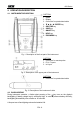
400 Series 4. OPERATION DESCRIPTION 4.1. INSTRUMENT DESCRIPTION CAPTION: 1. Inputs 2. Display 3. Connector for optoisolated cable 4. ,, , / ENTER key 5. GO/STOP key 6. SAVE key 7. ON/OFF key 8. HELP key 9. ESC/MENU key Fig. 1: Description of the front part of the instrument CAPTION: 1. Connector for remote probe 2. E, N, P inputs 3. In1 input Fig. 2: Description of the upper part of the instrument CAPTION: 1. Connector for optoisolated cable Fig. 3: Description of the instrument’s side 4.2.
400 Series 4.3.
400 Series 5. MAIN MENU Pressing the MENU/ESC key in any allowable condition of the instrument displays the following screen, in which the instrument may be set, the saved measures can be displayed and the desired measuring function may be set. AUTO LOW M RCD LOOP Ra 123 AUX LEAK PWR SET MEM : : : : : : : : : : : : MENU Ra, RCD, M continuity insulation RCD test impedance earth r e s . PH sequence environment leakage curr. analyzer settings memory 5.1.
400 Series 5.2.2. Auto power off Move the cursor to Auto power off by means of the arrow O F F keys (,) and confirm with ENTER. Subsequently, the displays shows the setting screen which allows enabling/disabling the auto power off of the instrument after a O N 5 m i n period of 5 minutes inactivity. OFF Select the desired option by means of the arrow keys (,). To store settings, press the ENTER key, to exit the changes made, press the ESC key. VAL 5.2.3.
400 Series 6. ELECTRICAL SYSTEM TEST Press (short pressure) the key to activate the display’s backlighting should it be difficult to read the display. Press (long pressure) the HELP key to display an indicative scheme of the connections between the instrument and the system being tested in the function set Should more help screens be available for the same function, use the and keys to scroll them. Press the ESC key to exit the on-line help and go back to the selected measurement. 6.1.
400 Series 1. Press the MENU key, move the cursor to AUTO in the main menu by means of the arrow keys (,) and confirm with ENTER. Subsequently the instrument displays a screen similar to the one reported here to the side. AUTO Ra = ---- Trcd = ----ms RP-Pe = ----M 30mA IdN 2. RCD 50V 500V UL VNom Use the , keys to select the parameter to be modified, and the , keys to modify the parameter value. It is not necessary to confirm the selection with ENTER.
400 Series CAUTION If message “Measuring…” appears on the display, the instrument is performing measurement. During this whole stage, do not disconnect the test leads of the instrument from the mains. 5. 6. Once the test is completed, if all measured values are correct, the instrument gives a double acoustic signal and displays the message “OK”, which signals that the test has been completed successfully, and a screen similar to the one reported here to the side AUTO Value of earth resistance Ra = 49.
400 Series 4. 5. The results displayed can be saved by pressing the SAVE key twice or the SAVE key and, subsequently, the ENTER key (§ 9.1) If the instrument detects that the phase and neutral leads are inverted, the message reported here to the side is displayed. Rotate the shuko plug or check the connection of the single cables AUTO Ra = ---- Trcd = ----ms RP-Pe = ----M 30mA IdN 6.
400 Series 6.2. LOWOHM: CONTINUITY TEST OF EARTH LEADS WITH 200mA This function is performed in compliance with standard IEC/EN61557-4 and allows measuring the resistance of protective and equipotential conductors. The following operating modes are available: compensation of the resistance of the cables used for measurement. The instrument automatically subtracts the value of cable resistance from the measured resistance value.
400 Series 2. Use the , keys to select the parameter to be modified, and the , keys to modify the parameter value. It is not necessary to confirm the selection with ENTER. Func The virtual Func key allows setting the measuring mode of the instrument, which may be: CAL, AUTO, R+, R- Lim The virtual Lim key allows setting the maximum continuity limit, which may have the following values: 1.00, 2.00, 3.00, 4.00, 5.00 3.
400 Series 10. 11. 12.
400 Series 4. 5. Once calibration is completed, in case the detected value is lower than 5, the instrument gives a double acoustic signal which signals the positive result of the test and displays a screen similar to the one reported here to the side LOW ---- R+ ---- ---mA R---- ---mA CAL 4.00 0.
400 Series 5. If the instrument detects a voltage value higher than 10V at the input leads, the screen reported here to the side is displayed LOW ---- R+ ---- ---mA R---- ---mA Vin > Vlim AUTO Func 6. 7. 8. 9. In case it was detected that the calibrated resistance is higher than the measured resistance increased by 0.05 (RCAL>RMEAS+0.
400 Series 6.3. M: MEASUREMENT OF THE INSULATION RESISTANCE This function is performed according to standard IEC/EN61557-2 and allows measuring the insulation resistance between the active conductors and between each active conductor and the earth. The following operating modes are available: MAN in this mode, the test continues until the GO/STOP key on the instrument (or the START key on the remote probe) is held.
400 Series 2. Use the , keys to select the parameter to be modified, and the , keys to modify the parameter value. It is not necessary to confirm the selection with ENTER.
400 Series 9. In case the TMR mode has been selected, pressing the GO/STOP key on the instrument or the START key on remote probe stops the test before the set time has elapsed. 10. Should the measured value be higher than the set limit, the instrument gives a double acoustic signal and displays the message “OK” which signals the positive result of the test and a screen similar to the one reported here to the side M 11. Should the measured value be higher than the full scale (§ 12.
400 Series 3. 4. The results displayed can be saved by pressing the SAVE key twice or the SAVE key and, subsequently, the ENTER key (§ 9.1) If the instrument detects a voltage of about 10V on the upper input leads, it displays the message reported here to the side and stops measurement M ---M ----V ---s Vin > Vlim MAN Func 5. 500V VNom 0.
400 Series 6.4. RCD: TEST ON A-TYPE AND AC-TYPE RCDS This function is performed in compliance with standard IEC/EN61557-6 and allows measuring the tripping time and the current of the system’s RCDs. The following operating modes are available: AUTO the instrument performs measurement automatically with a leakage current equal to half, once or five times the set value of nominal current and with a leakage current in phase with the positive and negative half-wave of the mains voltage.
400 Series Fig. 12: Instrument connection for 400V + N + PE three-phase RCD test by means of single cables and remote probe Fig. 13: Instrument connection for 400V + N (no PE) three-phase RCD test by means of single cables and remote probe Fig. 14: Instrument connection for 400V + PE (no N) three-phase RCD test by means of single cables and remote probe 1. 2. Press the MENU key, move the cursor to RCD in the main menu by means of the arrow keys (,) and confirm with ENTER.
400 Series RCD The virtual RCD key enables the selection of the RCD type, which may be: AC, AC S, A, A S (the options A, A S are not available if the electrical system set is IT) UL The virtual UL key allows setting the limit value of contact voltage for the system being tested, which may be: 25V, 50V 3. Should you have any doubt regarding the correct value, we suggest setting the limit value for contact voltage to 25V, as it is the lowest limit (for safety reasons). 4.
400 Series 7. Once test is completed, in case all six tests have had a positive result, the instrument displays a screen similar to the one reported here to the side RCD 0° 180° x1/2 >999ms >999ms x1 28ms 31ms x5 8ms 10ms FRQ=50.0Hz Ut=1.4V VP-N=228V VP-Pe=228V Tripping times (expressed in ms) RCD OK AUTO Func 30mA IdN RCD 50V UL The results displayed can be saved by pressing the SAVE key twice or the SAVE key and, subsequently, the ENTER key (§ 9.1) 8. 6.4.2. x½ mode As an alternative: 5.
400 Series 6.4.3. x1, x2, x5 mode As an alternative: 5. Press the GO/STOP key on the instrument or the START key on the remote probe once. The instrument will start measuring with a “0°” type current, injecting a current in phase with the positive half-wave of voltage. 5. Press the GO/STOP key on the instrument twice or the START key on the remote probe before the hyphens disappear.
400 Series CAUTION If message “Measuring…” appears on the display, the instrument is performing measurement. During this whole stage, do not disconnect the test leads of the instrument from the mains. 6. According to standard EN61008, the test for selective RCDs requires an interval of 60 seconds between the tests. The mode is therefore unavailable for selective RCDs, both of A and of AC type. 7.
400 Series 6. After the test is completed, if R C D the measured resistance value matches the nominal Value of total earth resistance current and the set limit Detected value for contact voltage Ut contact voltage, RA
400 Series 4. If the selective RCD trips in a R C D 0° time lower than the minimum limit reported in Tab. 5, the instrument gives a long acoustic signal which signals FRQ=50.0Hz Ut=1.4V the negative result of the test V P - N = 2 2 1 V V P - P e = 2 2 1 V and then displays a screen TIME NOT OK similar to the one reported 50V x1 30mA S here to the side. Check that Func IdN RCD UL the set type of RCD matches the type of RCD being tested 97ms 5.
400 Series 9. If the instrument detects that R C D the phase and earth leads are inverted, the message reported here to the side is displayed. Check the FRQ=50.0Hz connection of the cables VP-N= 1V 0° ---ms Ut=1.4V VP-Pe=231V The phase and earth conductors are inverted REVERSE P-PE x1 Func 30mA IdN RCD 50V UL 10. If the instrument detects a R C D 0° phase-to-neutral voltage and a phase-to-earth voltage lower than the limit, the message reported here to FRQ=50.0Hz Ut=1.4V the side is displayed.
400 Series 14. If the instrument detects that, in R C D 0° case the test should be performed, a contact voltage higher than the set limit would build up in the system being FRQ=50.0Hz Ut=0.0V tested, it does not perform the V P - N = 2 3 1 V V P - P e = 2 3 1 V test and displays the message Ut > Ulim reported here to the side. 30mA 50V Check the efficiency of the x1 Func IdN RCD UL protective conductor and the earthing ---ms The instrument detects a dangerous contact voltage 15.
400 Series 6.5. LOOP: MEASUREMENT OF LINE/LOOP IMPEDANCE This function is performed according to standard IEC/EN61557-3 and allows measuring the line impedance, the earth fault loop impedance and the prospective short circuit current.
400 Series Fig. 18: Instrument connection for 400V + N + PE three-phase P-P line impedance measurement by means of single cables and remote probe Fig. 19: Instrument connection for 400V + PE (no N) three-phase P-PE fault loop impedance measurement through single cables and remote probe 1. 2. Press the MENU key, move the cursor to LOOP in the main menu by means of the arrow keys (,) and confirm with ENTER. Subsequently the instrument displays a screen similar to the one reported here to the side.
400 Series RMT The virtual RMT key, active only when the Z2Ω mode has been selected with the MOD key, displays the serial number and the FW version of the remote unit IMP57 3. If possible, disconnect all loads connected downstream of the measured point, as the impedance of these users could distort the test results. 4. Use the virtual Mod. key to set the STD test mode.
400 Series 8. Formula used for calculating the prospective short circuit current: I CC where: UN Z PN ZPN is the measured phase-to-neutral impedance UN is the nominal phase-to-neutral voltage UN = 127V if VP-N meas ≤ 150V UN = 230V or UN = 240V (§ 5.2.3) if VP-N meas > 150V The results displayed can be saved by pressing the SAVE key twice or the SAVE key and, subsequently, the ENTER key (§ 9.1) 9. 6.5.2. P-P mode Press the GO/STOP key on the instrument or the START key on remote 6. probe.
0 Series 6.5.3. P-PE mode in TT or TN systems As an alternative: Press the GO/STOP key on the instrument or the START key on remote probe once. The instrument will start measuring with a 6. “0°” type current, injecting a current in phase with the positive half-wave of voltage Or: Press the GO/STOP key on the instrument twice or the START key on the remote probe before the hyphens disappear. The instrument 6.
400 Series 6.5.4. P-PE mode in IT systems Press the GO/STOP key on the instrument or the START key on remote 6. probe. The instrument will start the measurement. CAUTION If message “Measuring…” appears on the display, the instrument is performing measurement. During this whole stage, do not disconnect the test leads of the instrument from the mains. 7. Once test is completed, if the L O O P measured contact voltage value is lower than the set limit, the instrument gives a Ut=19.
400 Series 4. If the instrument detects that L O O P the phase and earth leads are inverted, the message reported here to the side is ---A displayed. Check the FRQ=50.0Hz connection of the cables VP-N= 1V VP-Pe=231V ---- REVERSE P-PE P-N Func 5. The phase and earth conductors are inverted STD Mod. If the instrument detects a L O O P phase-to-neutral voltage and a phase-to-earth voltage lower than the limit, the ---A message reported here to FRQ=50.0Hz the side is displayed.
400 Series 9. By using the P-PE mode, if L O O P 0° the instrument detects that, in case the test should be performed, a contact voltage ---A higher than the set limit FRQ=50.0Hz would build up in the system V P - N = 2 3 1 V V P - P e = 2 3 1 V being tested, it does not Ut > Ulim perform the test and displays STD the message reported here P-PE Func Mod. to the side. Check the efficiency of the protective conductor and the earthing ---- 10.
400 Series 6.6. RA 15MA: MEASUREMENT OF THE TOTAL EARTH RESISTANCE THROUGH THE SOCKET-OUTLET This function is performed in compliance with standards IEC/EN61557-6 and allows measuring the impedance of the fault loop, comparable to the overall earth resistance in TT systems. One single operating mode is available. CAUTION The measurement of the overall earth resistance involves the circulation of a current between phase and earth according to the technical specifications of the instrument (§ 12.1).
400 Series 1. Press the MENU key, move the cursor to Ra in the main menu by means of the arrow keys (,) and confirm with ENTER. Subsequently the instrument displays a screen similar to the one reported here to the side. Ra ----- ----A FRQ=50.0Hz VP-N=228V VP-Pe=228V 50V UL 2. Use the arrow keys , to set the limit value of contact voltage for the system being tested, which may be: 50V, 25V. It is not necessary to confirm the selection with ENTER. 3.
400 Series 7. Formula used for calculating the prospective fault current: I CC where: 8. 9. UN Z PE ZPE is the measured fault impedance UN is the nominal phase-to-earth voltage UN = 127V if VP-PE meas ≤ 150V UN = 230V or UN = 240V (§ 5.2.3) if VP-PE meas > 150V In TT systems, the impedance value measured by the instrument may only be referred to the value of the total earth resistance.
400 Series 5. If the instrument detects that R a the phase and earth leads are inverted, the message reported here to the side is ---A displayed. Check the FRQ=50.0Hz connection of the cables VP-N= 1V VP-Pe=231V ---- REVERSE P-PE The phase and earth conductors are inverted 50V UL 6. If the instrument detects a R a phase-to-neutral voltage and a phase-to-earth voltage lower than the limit, the ---A message reported here to FRQ=50.0Hz the side is displayed.
400 Series 9. If the instrument detects an R a extremely high earth resistance, so that it deems the earth conductor or the ---A earthing absent, it does not FRQ=50.0Hz perform the test and displays V P - N = 2 3 1 V V P - P e = 1 6 0 V the message reported here MISSING-PE to the side. Check the efficiency of the protective 50V UL conductor and the earthing ---- 10.
400 Series 6.7. 123: PHASE SEQUENCE TEST This function is performed in compliance with standards IEC/EN61557-7 and allows testing the phase sequence by direct contact with parts under voltage (no cables with insulating sheath). The following operating modes are available: 1T 2T one test lead mode two test leads mode. Fig. 24: Instrument connection for measuring the phase sequence with one lead, phase 1 connection Fig.
400 Series CAUTION If message “Measuring…” appears on the display, the instrument is performing measurement. During this whole stage, do not disconnect the test leads of the instrument from the mains. 5. The instrument switches to stand-by mode and displays the screen reported here to the side until the test lead detects a voltage higher than the minimum limit value 123 --Waiting phase 1 Waiting for phase 1 1T Func 6. 7. 8.
400 Series Fig. 27: Instrument connection for measuring the phase sequence with two leads, phase 2 connection 9. When the instrument detects a voltage higher than the minimum limit value on the test lead, the instrument displays the screen reported here to the side and starts measuring the second voltage. The instrument gives a long acoustic signal until input voltage is present 123 10.
400 Series 6.7.1. Description of anomalous results 1. Once acquisition is completed, if the instrument has detected an uncorrect phase sequence, it displays a screen similar to the one reported here to the side and gives a long acoustic signal 123 132 Correct phase sequence NOT OK 1T Func 2. 3. 4. The results displayed can be saved by pressing the SAVE key twice or the SAVE key and, subsequently, the ENTER key (§ 9.
400 Series 7. AUXILIARY MEASUREMENTS 7.1.
400 Series 7.1.1. dB mode 3. Connect the sound level probe to the instrument’s optical input by means of the optical cable 4. Press the GO/STOP key. The instrument starts A U X measuring the acoustic pressure. The following SPL ---dB values are displayed: SPL acoustic pressure Peak ---dB Peak acoustic pressure peak Duration time elapsed since the D u r a t i o n 0 0 0 0 : 0 0 : 0 0 beginning of the recording dB Func 5. Press the GO/STOP key again.
400 Series 7.1.2. AIR, RH, TMP °F, TMP °C, Lux mode 3. Insert the connector of the probe being used into the instrument input In1 making sure that the probe connected and the set measurement unit correspond 4. Press the GO/STOP key. The instrument stops A U X updating the measured value and STOP appears on the right bottom part of the display. I n 1 Press the same key again to restart the measurement and the real-time display of the instant value of the input parameter.
400 Series 7.2. LEAK: REAL TIME MEASUREMENT OF THE LEAKAGE CURRENT THROUGH AN EXTERNAL CLAMP Using an external clamp, this function allows measuring the leakage current. Fig. 30: Indirect measurement of leakage current in three-phase systems Fig. 31: Direct measurement of leakage current in three-phase systems 1. Press the MENU key, move the cursor to L E A K LEAK in the main menu by means of the arrow keys (,) and confirm with ENTER.
400 Series CAUTION Possible additional earth connections could influence the measured value. For the difficulty of this measurement and the sometimes real difficulty in removing the clamps, we recommend performing the measurement indirectly. 6. Press the GO/STOP key. The instrument stops L E A K updating the measured value and STOP appears on the right bottom part of the display.
400 Series 8. MAINS ANALYSIS 8.1. PWR: REAL TIME MEASUREMENT OF THE MAINS PARAMETERS This function allows measuring the voltage of the electrical mains and of the relevant harmonics. Using an external clamp, it is also possible to measure the current and the relevant harmonics as well as other electrical parameters such as power, power factor, etc. The following operating modes are available: PAR HRM V HRM I measurement of electrical parameters such as current, voltage, power, power factor, etc.
400 Series hxx The virtual FS key, active only when the HRM V or the HRM I mode has been selected with the Func key, allows increasing or decreasing the ordinal harmonic number whose value is displayed 3. Insert the clamp connector into the instrument input In1 4. Staple the phase to be tested. Insert both the black and blue connectors of the single cables into the relative P and N instrument input leads.
400 Series 9. MEMORY 9.1. HOW TO SAVE A MEASURE 1. When the SAVE key is first S A V E pressed, as described in the Memory: 015 §s regarding the different Position: 010 measurements, the instrument displays a screen Location: 194 similar to the one on the side P First available memory location (last saved + 1) Last P parameter set value Last L parameter set value L 2.
400 Series 9.2. SAVED DATA MANAGEMENT 1. Press the MENU key, move the cursor to MEM in the main menu by means of the arrow keys (,) and confirm with ENTER.
400 Series 9.2.2. How to delete the last measure or all of them 3. By means of the CANC virtual key select LST or TOT whether you want to delete the last measure or all the measures in the memory. Subsequently, press the ENTER key. The instrument asks for a confirmation of the deletion by displaying a screen similar to the one reported here to the side As an alternative: 4. Press the ENTER key to confirm deletion of the measures.
400 Series 10. CONNECTING THE INSTRUMENT TO A PC The instrument can be connected to a PC via a serial port or USB and an optoisolated cable. Before connecting, it is necessary to select the port to be used and the right baud rate (9600 bps) on the PC. To set these parameters, start the software and refer to the program's on-line help. The selected port must not be engaged by other devices or applications, e.g. a mouse, a modem, etc. To transfer the saved data to the PC, follow this procedure 1.
400 Series 11. MAINTENANCE 11.1. GENERAL The instrument you purchased is a precision instrument. When using and storing it, please observe the recommendations listed in this manual in order to prevent any possible damage or danger. Do not use the instrument in environments with high humidity levels or high temperatures. Do not directly expose it to sunlight. Always switch off the instrument after using it.
400 Series 12. SPECIFICATIONS 12.1. TECHNICAL FERATURES Continuity test (LOW) Range [] 0.00 9.99 10.0 99.9 Uncertainty Resolution [] 0.01 0.1 (2.0rdg + 2dgt) Test current >200mA DC up to 5 (include the resistance of the calibration) also with half-charged battery Generated current resolution 1mA, uncertainty (5.
400 Series Tripping current ( ) IdN [mA] Type AC ≤ 10 A AC > 10 A RCD type Tripping time Range IdN [mA] (0.5 1.1) IdN (0.3 1.1) IdN (0.5 1.1) IdN (0.3 1.1) IdN AC ( ), A ( resolution 1ms, Uncertainty 0.1IdN -0%, +10%rdg ), general and selective uncertainty (2.0%rdg + 2dgt) Earth resistance (Ra) Range [] 1 1999 RCD type Test current Contact voltage Ut Resolution [mA] Resolution [] 1 Uncertainty (5.
400 Series Environmental parameters (AUX) Parameter Temperature Humidity DC voltage Luminance Range Resolution -20.0 80.0°C -4.0 176.0°F 0.0 100.0% RH (0.0 999.9mV) 0.001 20.00Lux 0.1 2000Lux 1 20000Lux 0.1°C 0.1°F 0.1% RH 0.1mV 0.001 0.02Lux 0.1 2Lux 0.1 2Lux Transduced signal -20 +80mV -4 +176mV 0 +100mV (0.2 999.9mV) 0 +100mV 0 +100mV 0 +100mV Uncertainty (2.0rdg + 2dgt) Mains analisys (PWR) Frequency measurement Range [Hz] 47.0 63.0 Resolution [Hz] 0.
400 Series Measurement of the active, reactive and apparent power @ Vmis>60V, cos=1, f=50.0Hz Clamp full scale Range [W, VAR, VA] Resolution [W, VAR, VA] Uncertainty [A] 0.1 0.0 999.9 FS ≤ 1 0.001 k 1.000 9.999 k 0.001 k 0.000 9.999 k 1 < FS ≤ 10 0.01 k 10.00 99.99 k (1.0rdg + 6dgt) 0.01 k 0.00 99.99 k 10 < FS ≤ 100 0.1 k 100.0 999.9 k 0.1 k 0.0 999.9 k 100 < FS ≤ 3000 1k 1000 9999 k Measurement of the power factor (cos) @ Vmis>60V, f=50.0Hz Current range [A] Range Resolution 0.005 0.
400 Series 12.2. SAFETY SPECIFICATION 12.2.1. General Instrument safety: IEC/EN61010-1, IEC / EN61557-1, -2, -3, -4, -6, -7 Technical documentations: IEC/EN61187 Accessory safety: IEC/EN61010-031, IEC/EN61010-2-032 Insulation: double insulation Pollution level: 2 Max height of use: 2000m (6562ft) Overvoltage category: CAT III 240V to earth, max 415V among inputs P, N, PE 5V to ground, max 7.2Vpeak to peak between pins of In1 Input 12.2.2.
400 Series 13. SERVICE 13.1. WARRANTY CONDITIONS This instrument is guaranteed against any defect in material and manufacturing in compliance with the general sales terms and conditions. Throughout the period of guarantee all defective parts may be replaced and the manufacturer reserves the right to repair or replace the product. If the instrument is to be returned to the after-sales service or to a dealer transportation costs are on the customer’s behalf. Shipment shall be however agreed upon.
400 Series 14. PRACTICAL REPORTS FOR ELECTRICAL TESTS 14.1. CONTINUITY MEASUREMENT ON PROTECTIVE CONDUCTORS 14.1.1. Purpose of the test Check the continuity of: Protective conductors (PE), main equalizing potential conductors (EQP), secondary equalizing potential conductors (EQS) in TT and TN-S systems Neutral conductors having functions of protective conductors (PEN) in TN-C system.
400 Series 14.2. INSULATION RESISTANCE MEASUREMENT 14.2.1. Purpose of the test Check that the insulation resistance of the installation complies with the requirements of IEE 16th edition standard. EXAMPLE OF INSULATION MEASUREMENT ON AN INSTALLATION Fig. 34: Insulation measurements on an installation The switches D and E are those installed near the load having the purpose of separating it from the installation.
400 Series Switch situation 1. 2. Turn the switch A, D and E off Turn the switch B off Point under test Effect the measurement on switch A Effect the measurement on switch A 3. Effect the measurement on switch B 4. Effect the measurement on switch B 5.
400 Series ALLOWABLE VALUES Test voltage (V) Insulation resistance (M) SELV and PELV* 250 0.250 Up to 500 V included, except for the above circuits. 500 1.000 1000 1.000 Rated circuit voltage (V) Over 500 V * In the new standards the terms SELV and PELV replace the old definitions "safety low voltage" or "functional". Tab.
400 Series 14.3. CHECK OF THE CIRCUIT SEPARATION 14.3.1. Definitions A SELV system is a system of category zero or very low safety voltage featured by: autonomous source (ex. batteries, small generator) or safety (ex. safety transformer) power supply, protection separation to other electrical systems (double or reinforced insulation or a metal screen connected to the earth) and no earthed points (insulated from the earth).
400 Series EXAMPLE OF CHECKING THE SEPARATION AMONG ELECTRICAL CIRCUITS Insulation or safety transformer separating the circuits TEST BETWEEN ACTIVE PARTS Connect an instrument probe to one of the two conductors of the separated circuit and the other to one of the conductors of a nonseparated circuit TEST BETWEEN ACTIVE PARTS AND EARTH Connect an instrument probe to one of the two conductors of the separated circuit and the other to the equalizing potential node.
400 Series 14.4. WORKING TEST OF RCDS 14.4.1. Purpose of the test Check whether general and selective RCDs have been installed and adjusted properly and whether they maintain their features over the time. The check shall confirm that the RCD trips at a current IdN lower than its rated working current IdN and that the tripping time meets, depending on the case, the following conditions: Does not exceed the maximum time provided by the standards in case of general type RCDs (according to Tab. 5).
400 Series Before effecting the test at the RCD rated current the instrument carries out a test at ½IdN to measure the contact voltage and the overall earth resistance; if during this test the RCD trips an error message is displayed. During this test the RCD may trip for three possible reasons: the RCD tripping current is lower than ½ IdN an earth plate is already present on the installation which added to the earth generated by the instrument causes the RCD tripping.
400 Series 14.6. MEASUREMENT OF SHORT-CIRCUIT IMPEDANCE 14.6.1. Purpose of the test Check that the tripping power of the protection device is higher than the maximum fault current of the installation. 14.6.2. Installation parts to be checked The test shall be effected in the point where the short circuit current is the highest possible, usually immediately downstream the RCD to be checked.
400 Series 14.8. EARTH RESISTANCE MEASUREMENTIN TT SYSTEMS 14.8.1. Purpose of the test Check that the RCD is coordinated with the earth resistance value. It is not possible to assume an earth resistance value as reference limit when controlling the test result, while it is necessary to check every time that the co-ordination complies with the requirements of the standards. 14.8.2. Installation parts to be checked The earth installation under working conditions.
400 Series 14.9. VOLTAGE AND CURRENT HARMONICS 14.9.1. Theory Any periodical non-sine wave can be represented as a sum of sinusoidal waves having each a frequency that corresponds to an entire multiple of the fundamental, according to the relation: v(t) V0 Vk sin( k t k ) k 1 where: (1) V0 = average value of v(t) V1 = amplitude of the fundamental of v(t) Vk = amplitude of the kth harmonic of v(t) LEGEND: 1. Fundamental 2. Third harmonic 3. Distorted waveform Fig.
400 Series Odd harmonics Not multiple of 3 Multiple of 3 Order h Relative voltage Order h Relative voltage % Max % Max 5 6 3 5 7 5 9 1,5 11 3,5 15 0,5 13 3 21 0,5 17 2 19 1,5 23 1,5 25 1,5 Even harmonics Order h Relative voltage % Max 2 4 6..24 2 1 0,5 Tab.
400 Series 14.9.4. Presence of harmonics: consequences nd th In general, even harmonics, i.e. the 2 , 4 etc., do not cause problems. Triple harmonics, odd multiples of three, are added on the neutral (instead of cancelling each other) thus creating a condition of overheating of the wire which is extremely dangerous.
400 Series In presence of distorted voltages and currents the previous relations vary as follows: Phase active power: (n=1,2,3) Pn Vk n I k n cos ( k n ) k 0 Phase reactive power: Qn S n2 Pn2 (n=1,2,3) Phase apparent power: S n VnN I n (n=1,2,3) Phase power factor: PF n (n=1,2,3) Distorted power factor (n=1,2,3) dPFn = cosf1n = QTOT Q1 Q2 Q3 Total reactive power: S TOT PTOT QTOT 2 PF TOT Total power factor: where: phase displacement between the fundamentals o
400 Series Equipment under test = inductive generator Equipment under test = capacitive load 90° 180° P+ Pfc+ Pfi+ Qc+ Qi+ P+ Pfc+ Pfi+ Qc+ Qi+ = = = = = = = = = = 0 -1 -1 0 0 0 -1 -1 0 0 PPfcPfiQcQiPPfcPfiQcQi- = = = = = = = = = = P -1 Pf 0 Q P Pf -1 Q 0 P+ Pfc+ Pfi+ Qc+ Qi+ P+ Pfc+ Pfi+ Qc+ Qi+ = = = = = = = = = = P Pf -1 Q 0 P -1 Pf 0 Q PPfcPfiQcQiPPfcPfiQcQi - = = = = = = = = = = 0 -1 -1 0 0 0 -1 -1 0 0 0° 270° Equipment under test = capacitive generator Equipment under test = inductive
Via della Boaria 40 48018 – Faenza (RA) - Italy Tel: +39-0546-621002 (4 linee r.a.) Fax: +39-0546-621144 email: ht@htitalia.it http://www.ht-instruments.