
User guide


SOLAR300 - SOLAR300N
EN - 26
CAUTION
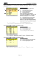
The Total Consumed Energy page is shown only if the instrument has been
set for the Recording of the General Parameter Total “Active Power &
Energy” (see § 5.4.2.7). Values will be shown only during or at the end of a
recording and zeroed upon starting a new recording or when the instrument
is switched off
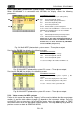
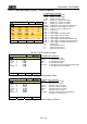
25/01/2013 – 16:55:10
TOT. ENERGY PRODUCTION – Page x/y
Eact = 0 kWh
Ppeak = 0 kW
Date Ppeak : -- / -- / -- 00:00:00
Start rec. : -- / -- / -- 00:00:00
Stop rec. : -- / -- / -- 00:00:00
Rec Time : - - -
Int. Per. : - - - Rec: - -
PAGE SCOPE HARM VECTORS
PARAMETERS CAPTION:
Eact Total active energy produced when starting
recording.
Ppeak Maximum peak of produced active power.
Date Ppeak Date and time in which the peak occurred.
Start rec. Date when recording was started.
Stop rec. Date when recording was stopped.
Rec Time Time elapsed from Rec Start.
Int. Per. Value of the set integration period.
Rec Number of the recording in progress
Fig. 43: Producted energy page
CAUTION
The Total Produced Energy page is shown only if recording parameter “Co-
generation” has been set in the instrument (see § 5.4.2.5) and if general
parameter Total “Active Power & Energy” has been selected (see § 5.4.2.7).
Values will be shown only during or at the end of a recording and zeroed
upon starting a new recording or when the instrument is switched off.
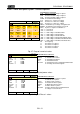
5.2.4.3. 3-wire ARON three phase system – Screens sequence
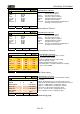
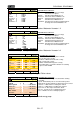
12/09/2006 – 16:55:10
TOTAL RMS VALUES – Page x/y
V12
0.0
V23
0.0
V31
0.0
V
NEG%
0.0
ZERO%
0.0
SEQ
000
Hz
0.0
I1
0.0
I2
0.0
I3
0.0
A
PAGE SCOPE HARM VECTORS
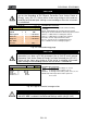
PARAMETERS CAPTION:
V12 Phase L1 – Phase L2 voltage
V23 Phase L2 – Phase L3 voltage
V23 Phase L3 – Phase L1 voltage
NEG% Unbalance percentage of negative tern
ZERO% Unbalance percentage of zero tern
SEQ phases sequence indication as:
”123” = > Corrected
”132” = > Reversed
”023” = > Null voltage on the Black wire
”103” = > Null voltage on the Red wire
”120” = > Null voltage on the Brown wire
”100” = > Null voltage on the Red and Brown wires
”020” = > Null voltage on the Black and Brown wires
”003” = > Null voltage on the Black and Red wires
Hz Frequency
I1 Current on L1 phase
I2 Current on L2 phase
I3 Current on L3 phase
Fig. 44: Page of numerical values