
User guide

SOLAR300 - SOLAR300N
EN - 184
10. APPENDIX – THEORETICAL OUTLINES
10.1. TESTING PV SYSTEMS
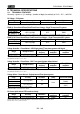
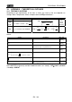
According to the requirements of the laws in force, the result of the test depends on
settings about Temperature effects compensation and PRp calculations :
Corr.T
y
pe Tcel value PRp calculation Guideline
Tmod Tcel = PV Module Temp. measured
n
STC
p
ca
P
G
G
Rfv
P
PRp
2
CEI
82-25
(Italian
Guideline)
Tamb
or
Tenv
Tcel = PV module Temp. calculated
800
G
20TambTcel
p
NOCT
nDC Tcel = PV Module Temp. measured
n
ca
cel
p
STC
P
P
T
G
G
PRp
25
100
1
- - -
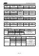
where:
Symbol Description Meas. unit
p
G
Irradiance on PV module surface
2
W/m
STC
G
Standard Irradiance = 1000
2
W/m
n
P
Nominal Power = sum of all power module (Pmax )
included in the part of PV plant under test
kW
ca
P
AC Active Power measured
kW
C)40Tcel (if
100
40)-(Tcel- 1
C)40Tcel (if 1
2
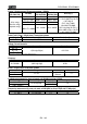
Rfv
Thermal Corrective factor
Absolute value of Pmax thermal coefficient
C%/
NOCT Normal Operating Cell Temperature (@ 800W/m
2
, 20°C,
AM=1.5, vel. Aria =1m/s).
C%/
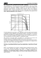
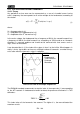
Previous relationship are valid if Irradiance > Min Irraddiance value (see user’s manual
of the MASTER instrument) and the Irradiance values are “steady”: if IP 1min (Irr max
– Irr min) < 20W/m
2