
User guide

SOLAR300 - SOLAR300N
EN - 138
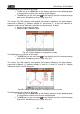
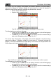
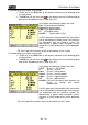
The following keys are active on this page:
The F1 key (or the PAG item on the display) advances to the following page
of saved values.
The ESC key (or the smart icon on the display) to exit the function and go
back to the “Recording analysis” page (Fig. 181).
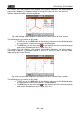
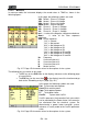
In this page, the following symbols are used:
V2PE Phase L2 - PE Voltage.
I2 Phase L2 current.
Patt2 Phase L2 active power.
Preatt2 Phase L2 reactive power.
Papp2 Phase L2 apparent power.
Pf2 Phase L2 power factor.
CosPhi2 Cosine of the phase delay between the
Phase L2 voltage and current
fundamentals.
CosPhi represents the theoretical limit value which
can be reached by the Power factor if all harmonics
are eliminated from the electrical system. For
dimensioning a power factor correction system,
reference is usually made to the CosPhi parameter
value.
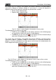
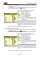
Fig. 225: Page 4/5 of numeric values for three-phase 3-wire system
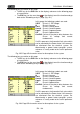
The following keys are active on this page:
The F1 key (or the PAG item on the display) advances to the following page
of saved values.
The ESC key (or the smart icon on the display) to exit the function and go
back to the “Recording analysis” page (Fig. 181).
In this page, the following symbols are used:
V3PE Phase L3 - PE Voltage.
I3 Phase L3 current.
Patt3 Phase L3 active power.
Preatt3 Phase L3 reactive power.
Papp3 Phase L3 apparent power.
Pf3 Phase L3 power factor.
CosPhi3 Cosine of the phase delay between the
Phase L3 voltage and current
fundamentals.
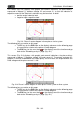
CosPhi represents the theoretical limit value which
can be reached by the Power factor if all harmonics
are eliminated from the electrical system. For
dimensioning a power factor correction system,
reference is usually made to the CosPhi parameter
value.
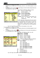
Fig. 226: Page 5/5 of numeric values for three-phase 3-wire system