
Instruction Manual

I-V400 - SOLAR I-V
EN - 19
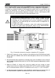
5.3. DB – MODULE DATABASE
The meter allows defining up to 30 different PV modules, further to a DEFAULT situation
(not editable and not erasable) which can be used as reference case when no piece of
information about the module under test is available.
The parameters which can be set, with reference to 1 module, are described below in
Table 1 together with their range, resolution and validity condition.
Symbol Description Range Resolution Condition
Nms Number of modules for string
1 50
1
Pmax Maximum nominal power of module
50 3200W
1W
01.0
max
max
P
IVP
mppmpp
Voc Open voltage
15.00 99.99V
100.0 320.0V
0.01V
0.1V
Voc Vmpp
Vmpp Voltage on point of maximum power
15.00 99.99V
100.0 320.0V
0.01V
0.1V
Voc Vmpp
Isc Short circuit current
0.5 9.99A
0.01A
Isc Impp
Impp Current on point of maximum power
0.5 9.99A
0.01A
Isc Impp
Toll -
Negative tolerance for Pmax provided
by the module manufacturer
0% 25.0%
0.1%
100*Tol
-
/Pnom< 25
0 99W
1
Toll +
Positive tolerance for Pmax provided
by the module manufacturer
0 25%
0.1%
100*Tol
+
/Pnom< 25
0 99W
1
Alpha Isc temperature coefficient
-0.1000.100%/°C
0.001%/°C
0.1*Alpha / Isc 0.1
-9.99 9.99mA/°C
0.01mA/°C
Beta Voc temperature coefficient
-0.99 -0.01%/°C
0.01%/°C
100*Beta/Voc 0.999
-0.999 0.001V/°C
0.001V/°C
Gamma Pmax temperature coefficient
-0.99 -0.01%/°C
0.01%/°C
NOCT Nominal working temperature of cell
0 100°C
1°C
Tech. Effects due to PV technology
STD (standard)
CAP(capacitive eff.)
Rs Internal serial resistance
0.00 10.00 0.01
Table 1: Typical parameters of PV modules
CAUTION
The “Tech” item is referred to the choose of the technology of the module
on test. Select the “STD” option for test on “STANDARD” PV modules or the
“CAP” option for test on higher capacitive effects PV modules (e.g. HIT/HIP
technology)
A
wrong choose of the type of technology can lead to a negative outcome of
the final test