User manual I-V400 - SOLAR I-V Copyright HT ITALIA 2012 Release EN 1.
I-V400 - SOLAR I-V Table of contents: 1. SAFETY PRECAUTIONS AND PROCEDURES .......................................................... 3 1.1. 1.2. 1.3. 1.4. 2. Preliminary instructions ..................................................................................................... 3 During use ......................................................................................................................... 4 After use .............................................................................
I-V400 - SOLAR I-V 7. STORING DATA ......................................................................................................... 58 7.1. 7.2. 7.3. Saving test results of PV checks (only SOLAR I-V) ........................................................ 58 Saving test results of I-V curve test ................................................................................. 58 Managing the results .................................................................................................
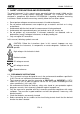
I-V400 - SOLAR I-V 1. SAFETY PRECAUTIONS AND PROCEDURES The word “instrument” in this manual means generically both the model I-V400 and the model SOLAR I-V except notation specifically indicated. This instrument has been designed in compliance with directives IEC/EN61010-1 regarding electronic measuring instruments.
I-V400 - SOLAR I-V 1.2. DURING USE We recommend to carefully read the following recommendations and instructions: CAUTION Failure to comply with the CAUTIONs and/or instructions may damage the instrument and/or its components or cause dangers to the operator. The symbol “ ” indicates the charge level. When there are five bars, it means that batteries are fully charged; a decrease in the number of bars down to “ ” indicates that the batteries are almost low.
I-V400 - SOLAR I-V 2. GENERAL DESCRIPTION 2.1. INTRODUCTION The instrument was designed to perform complete yield test on single-phase (and threephase if combined with optional accessory MPP300) PV installations with calculations of efficiencies (only SOLAR I-V) and to perform all I-V curve tests on single modules (panels) or complete strings of photovoltaic (PV) plants in order to verify the reference parameters given by the manufacturers.
I-V400 - SOLAR I-V 3. PREPARATION FOR USE 3.1. INITIAL CHECKS Before shipment, the instrument’s electronics and mechanics have been carefully checked. All possible precautions have been taken to have the instrument delivered under optimal conditions. However, we recommend to rapidly check the instrument in order to detect possible damage occurred during transport. Should you detect anomalies, please immediately contact the dealer.
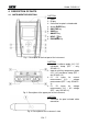
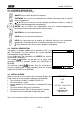
I-V400 - SOLAR I-V 4. DESCRIPTION OF PARTS 4.1. INSTRUMENT DESCRIPTION CAPTION: 1. Inputs 2. Display 3. Connector for opto insulated cable 4. Arrows/ENTER key 5. GO/STOP key 6. SAVE key 7. ON/OFF key 8. HELP / key 9. ESC/MENU key Fig. 1: Description of the front part of the instrument CAPTION: 1. Input for irradiance probe (I-V) / DC transducer clamp (EFF – only SOLAR I-V) 2. Input for auxiliary temperature probe (I-V) / AC transducer clamp (EFF – only SOLAR I-V) 3.
I-V400 - SOLAR I-V 4.2.
I-V400 - SOLAR I-V 5. MAIN MENU Pressing the MENU/ESC key in any allowable condition of the instrument displays the main menu screen, in which the instrument may be set, the saved measures can be displayed and the desired measuring function may be set (item EFF only appears for instrument SOLAR I-V). 15/05/10 15:34:26 I-V I-V Test EFF Yield Test SET Settings DB Modules Select by cursor the desired options and confirm by pressing MEM ENTER PC Data Recall PC connection ENTER to select. MENU 5.1.
I-V400 - SOLAR I-V 5.1.2. Measurement units This § allows setting the default measurement units of some internal parameters included in the database (DB) for the management of PV modules (§ 5.3) 1. Move the cursor to “Meas. Unit” by means of the arrow 15/05/10 15:34:26 keys (,) and confirm with ENTER. Parameter 2. The display shows the screen which allows selecting the measurement units of parameters shown by the meter. 3. Press ESC/MENU to exit without saving any setting. ENTER to select MENU 4.
I-V400 - SOLAR I-V 5.1.4. Remote unit This section allows selecting the type of remote unit to be used (if available) and setting the values of typical parameters (Sensitivity and Alpha) of the reference irradiance cell supplied with the meter. The values of these parameters, which are printed on the back label of the cell, depend on the type of PV modules on test. 1. Move the cursor to “Remote unit” by means of the arrow 15/05/10 15:34:26 keys (,) and confirm with ENTER Remote U EFF MPP300 2.
I-V400 - SOLAR I-V 5.1.5. Irradiance 1. Move the cursor to “Irradiance” by means of the arrow 15/05/10 15:34:26 keys (,) and confirm with ENTER. Irr min IV :0W/m2 2.
I-V400 - SOLAR I-V 5.2. EFF – SETTINGS FOR TESTING PV SYSTEMS (ONLY SOLAR I-V) Further in this manual, the acronym MPPT (Multiple Power Point Tracker) shall indicate the characteristic of the DC/AC converter (inverter), capable of maximizing the DC power which can be taken from the photovoltaic field. See § 11.2 for further details. 5.2.1.
I-V400 - SOLAR I-V 5.2.1.2. PV plant parameters 1. Press MENU key, move the cursor onto EFF by using the 15/05/10 15:34:26 arrow keys (,) and confirm with ENTER. The display P R p - - - - shows the values of the output electrical parameters of I r r Pnom 0.000 the photovoltaic generator (DC side). Tc - - Te Pdc Vdc Idc ndc Select - - - 0.0 0.000 0.0 - - - A GO – start rec EFF 2. Press the ENTER key. The instrument shows the 15/05/10 15:34:26 following options: “Set PV plant“ and “Set Instrum“.
I-V400 - SOLAR I-V 5.2.2. Settings for PV with single/multi MPPT inverter – single/three phase AC output See § 11.2 for further details about the meaning of MPPT. This mode requires unsing the remote unit MPP300 (optional). Check beforehand the settings made in MENUSETRemote Unit and check that you have selected “MPP300” as setting for parameter “R. unit”. 5.2.2.1. Instrument settings 1.
I-V400 - SOLAR I-V 5.2.2.2. PV plant parameters 1. Press MENU key, position the cursor onto EFF by using 15/05/10 15:34:26 the arrow keys (,) and confirm with ENTER. The P R p - - - - display shows the screen here to the side, which contains I r r Pnom 150.0 the global parameters of the system. Tc - - - Te Pdc Pac ndc nac Select - - GO – start rec. MPP 2. Press the ENTER key. The instrument shows the 15/05/10 15:34:26 following options: MPP300 status, Set PV plant.
I-V400 - SOLAR I-V 5.2.2.3. MPP300 status If SOLAR I-V is near MPP300, the general parameters of MPP300 may be displayed. 1. Position the cursor onto EFF by using the arrow keys 15/05/10 15:34:26 (,) and confirm with ENTER. The display shows the P R p - - - - screen here to the side, which contains the global I r r Pnom 1 5 0.0 parameters of the system. Tc - - Te Pdc Pac ndc nac - - - W/m2 kW °C °C kW kW GO – start rec. Select 2. Press the ENTER key.
I-V400 - SOLAR I-V 5.2.3. Selection of the compensation relationship of temperature effects This option allows selecting the relationship to be used to correct the measurements performed according to the modules’ temperature. The following correction modes are available: - T.mod.: Correction factor Rfv2 related to PV module Temp. (Italian guideline CEI-82-25) - T.env: Correction factor Rfv2 related to environment Temp.
I-V400 - SOLAR I-V 5.3. DB – MODULE DATABASE The meter allows defining up to 30 different PV modules, further to a DEFAULT situation (not editable and not erasable) which can be used as reference case when no piece of information about the module under test is available. The parameters which can be set, with reference to 1 module, are described below in Table 1 together with their range, resolution and validity condition.
I-V400 - SOLAR I-V 5.3.1. How to define a new PV module 1. Move the cursor to “DB” by means of the arrow keys 15/05/10 15:34:26 ype :DEFAULT (,) and confirm with ENTER. The display shows the T screen with: Pmax = 185 Voc = 44.5 The type of selected module Vmpp = 37.5 The parameter associated to the module (see Table 1) I s c = 5.40 = 4.95 2. Select the “DEFAULT” module by means of the arrow ITmo pl l p= 0 keys (,) and confirm with ENTER. Select DB 3.
I-V400 - SOLAR I-V 5.3.2. How to modify a PV module 1. Select the PV module to be modified from the internal 15/05/10 15:34:26 Type:SUNPOWER210 database by means of arrow keys (,). 2. Press the ENTER key and select the “Modify” command P m a x = 210 W Voc = 47.70 V by means the arrow key (). Vmpp = 40.00 V 3. Confirm the selection with ENTER. Isc = 5.75 A New Modify Delete Del. All Select DB 4.
I-V400 - SOLAR I-V 6. HOW TO OPERATE 6.1. TESTING PV SYSTEMS (ONLY SOLAR I-V) For the sake of simplicity, further in this manual, the word “string” will be used, although often the term “photovoltaic field” would be more correct. From the point of view of the instrument, the management of a single string or of more parallel strings (photovoltaic field) is identical.
I-V400 - SOLAR I-V 6.1.1. Testing of PV systems with single-MPPT inverter - single-phase AC output The SOLAR I-V meter (master) can perform check tests of efficiencies on single phase PV installations by using the irradiance and temperature probes which are connected to the remote unit SOLAR-02. This remote unit communicates with the master unit (for the synchronization and download data operations) through a wireless radio-frequency (RF) which is active with a maximum distance of about 1m between units.
I-V400 - SOLAR I-V 5. In case of inverters provided with more than one power tracker (MPPT), only leave the string corresponding to the first MPPT connected, as shown in Fig. 4. Then, it will be necessary to repeat the operations described below by only leaving the string corresponding to the second MPPT connected, then to the third, etc. 6. Bring SOLAR I-V and SOLAR-02 nearer (maximum distance of 1m between them). All instruments must be switched on (see the User Manual of SOLAR-2 for further details) 7.
I-V400 - SOLAR I-V 13. The display shows the first screen containing the values 15/05/10 15:34:26 of the electrical parameters on the DC side of the inverter. P R p - - Irr Pnom Tc Te Pdc Vdc Idc ndc - - - 3.500 45 30 3.125 389 8.01 - - - W/m2 kW °C °C kW V A Select GO – start rec. EFF 14. By means of arrow key to access to the second screen 15/05/10 15:34:26 with the values of electrical parameters of the AC side of Pdc 3.125 kW inverter. Before to start the recording: Vdc 389 V I d c 8 .
I-V400 - SOLAR I-V 17. At any time it will be possible to analyze the current 15/05/10 15:35:00 recording status by pressing the MENU key. The following S t a r t information will be shown: 14/02/00 17:18:00 P e r i o d : 5s starting date and time of recording IP Number 61 Rec. Time 0d 1h the value set for the integration period the number of periods elapsed from the beginning of the recording Rec.
I-V400 - SOLAR I-V 6.1.2. Test PV systems with single/multi-MPPT inverter – single/three-phase AC output The instrument SOLAR I-V, used together with remote units SOLAR-02 and MPP300 (optional), allows testing PV systems characterized by 1 or more strings (with the same direction and inclination) and single-phase or three-phase output.
I-V400 - SOLAR I-V CAUTION When SOLAR I-V is set in order to use MPP300 as a remote unit, ALL connections relevant to electrical quantities (voltages and currents) must be carried out on unit MPP300. SOLAR I-V must have no voltage nor current connected to its inputs. The maximum voltage for the inputs of MPP300 is 1000VDC between inputs VDC1, VDC2, VDC3 and 600VAC between inputs VAC1, VAC2, VAC3. Do not measure voltages exceeding the limits given in this manual.
I-V400 - SOLAR I-V 9. Connect the output connector of the DC clamp to the IDC1 input of unit MPP300. CAUTION BEFORE CONNECTING THE DC CLAMPS TO THE CONDUCTORS Switch on the clamp, check the LED indicating the status of the clamp’s internal batteries (if present), select the correct range, press the ZERO key on the DC clamp and check on the display of SOLAR I-V the actual zeroing of the corresponding Idc value (values up to 0.02A are acceptable). 10.
I-V400 - SOLAR I-V 18. On SOLAR I-V, press key () to access the second 15/05/10 15:34:26 screen which contains the values of the output DC V d c 1 460.1 parameters of the strings according to the number of DC V d c 2 461.4 Vdc3 462.5 inputs set (see § 5.2.1.1). In particular, in this screen: Idc1 Idc2 Idc3 Pdc1 Pdc2 Pdc3 Vdcx = DC voltage of string x Idcx = DC current of string x Pdx = DC power of string x.
I-V400 - SOLAR I-V 22. At any time it will be possible to analyze the current 15/05/10 15:35:00 recording status by pressing the MENU key. The following S t a r t information will be shown: 14/02/00 17:18:00 Period: IP Number Rec. Time Starting date and time of recording The value set for the integration period The number of periods elapsed from the beginning of the recording The remaining memory capacity for recording Select 5s 61 0d 1h Rec. Running MPP Press the ESC key to exit the screen 23.
I-V400 - SOLAR I-V 32. To stop testing, press the GO/STOP key on instrument 15/05/10 15:35:00 SOLAR I-V and confirm pressing ENTER that you want to PRp 0.815 Irr 971 stop recording. Pnom 3.500 33. The display of SOLAR I-V will show the message “DATA T c 45.1 DOWNLOAD” to indicate that the data will be transferred to T e 30.5 Pdc 3.125 the main unit during its various phases. Pac 2.960 ndc 0.806 34. After the automatic data transfer phase, the instrument: nac 0.
I-V400 - SOLAR I-V 6.2. I-V CURVE MEASUREMENT The meter can perform I-V curve tests by using one of the herewith modes: I-V curve test with Irr/Temp measurement directly performed by the instrument I-V curve test with Irr/Temp measurement performed by use of remote unit SOLAR-02 For theoretical information on measurement see the § 11.1 6.2.1. I-V curve measurement by use of instrument CAUTION The maximum voltage among P1, P2, C1, and C2 inputs is 1000V DC.
I-V400 - SOLAR I-V 9. Press ENTER key, select the “Settings” item and confirm 15/05/10 15:34:26 again with ENTER to access the next screen which allows V d c = 0.0 V setting the type of PV module and the number of modules Irr = - - - W/m2 relative to the PV string under test. Tc = - - - °C Module: PANEL01 Settings Meas. Type Select I-V 10.By means of arrow keys (,) select the type of PV 15/05/10 15:34:26 Type : SUNPOWER 210 module included in the database of meter (§ 5.3.1). N.of Mod. : 15 11.
I-V400 - SOLAR I-V 19. Connect the meter to the module/string under test as shown in Fig. 7a. In particular, connect the negative output pole of module/string to P1, C1 input terminals and the positive output pole of module/string to P2, C2 input terminals Fig. 7a: Instrument connection to module/string FV Fig. 7b: Positioning of inclinometer M304 CAUTION The method used by the instrument meter for output VDC and IDC measurements of PV module/string is the “4-wire”.
I-V400 - SOLAR I-V 22.At the end of test, the values of typical parameters (all 15/05/10 15:34:26 referred to a single module in standard conditions STC) Voc = 15.2 V are shown by the meter together with the final response (§ V m p p = 14.7 V = 4.7 A 6.2.3) based on the automatic calculation performed and I m p p Isc = 5.2 A relevant to: Pmax = 200 W FF = 77.1 % Translation of I-V curve to STC condition DPmax = 2.1 % Verification of tolerance % of the maximum power declared by the manufacturer.
I-V400 - SOLAR I-V 6.2.2. I-V curve measurement by use of remote unit SOLAR-02 The I-V curve test with Irr/Temp measurement by use of remote unit SOLAR-02 can be performed in one of the herewith mode: Remote unit SOLAR-02 in RF connection with main unit Remote unit SOLAR-02 in synchro recording (no RF connection with main unit) 6.2.2.1.
I-V400 - SOLAR I-V 9. The instrument displays a screen similar to the one reported here to the side, where: Vdc = DC output voltage from module/string Irr = irradiance measured by supplied reference cell Tc = temperature of module. The herewith options are available for this field: AUTO automatic mode of temperature measurement Number MAN or AUX mode of temp.
I-V400 - SOLAR I-V 16. Mount the M304 (inclinometer) supplied accessory, place and hold it on the plane of module. Verify that the sun shadow falls on the disc within the “limit internal circle” on the disc itself (see Fig. 8). If this is not the case, the incidence angle between sun rays and the module surface is too high and not complying with the test conditions declared by the module manufacturer.
I-V400 - SOLAR I-V 21.The instrument displays a screen similar to the one reported here to the side, where: Vdc = DC output voltage from module/string. Irr = irradiance measured by supplied reference cell Tc = temperature of module. The herewith options are available for this field: AUTO automatic mode of temperature measurement Number MAN or AUX mode of temp.
I-V400 - SOLAR I-V 6.2.2.2. I-V curve test by remote unit SOLAR-02 in synchro recording This mode, which consists in an independent recording of the irradiance and temperature parameters by the remote unit SOLAR-02, permits to perform I-V curve test also with wide distance between the instrument and SOLAR-02 without any connection between them.
I-V400 - SOLAR I-V 10.The instrument displays a screen similar to the one reported here to the side, where: Vdc = DC output voltage from module/string Irr = irradiance measured by supplied reference cell Tc = temperature of module. The herewith options are available for this field: AUTO automatic mode of temperature measurement Number MAN or AUX mode of temp.
I-V400 - SOLAR I-V 17. Mount the M304 (inclinometer) supplied accessory, place and hold it on the plane of module. Verify that the sun shadow falls on the disc within the “limit internal circle” on the disc itself (see Fig. 10). If this is not the case, the incidence angle between sun rays and the module surface is too high and not complying with the test conditions declared by the module manufacturer.
I-V400 - SOLAR I-V 22.The instrument displays a screen similar to the one reported here to the side, where: Vdc = DC output voltage from module/string Irr = irradiance measured by supplied reference cell Tc = temperature of module. The herewith options are available for this field: AUTO automatic mode of temperature measurement Number MAN or AUX mode of temp.
I-V400 - SOLAR I-V 25.At the end of test, based on the descriptions of previous 15/05/10 points, the message “STC Data available after Stop rec” is Voc displayed and then the results at OPC conditions are V m p p Impp displayed Isc Pmax FF Irr Tc 15:34:26 = = = = = = = = 15.2 14.7 4.7 5.2 200 77.1 - - Auto V V A A W % W/m2 Results @ OPC Select I-V 26.Press ENTER for the visualization of measurement results 15/05/10 15:34:26 both in numeric and graphical mode (§ 6.2.3) Voc = 15.2 27.
I-V400 - SOLAR I-V 6.2.3.
I-V400 - SOLAR I-V 6.2.4. Serial resistance Rs The serial resistance Rs is one of the typical elements of PV modules which can affect the I-V curve measurement of the panels themselves. The instrument meter performs the Rs calculation, during the measurement of I-V curve (§ 6.2.1), in the following modes: AUTOMATIC mode the Rs calculation is automatically performed by meter using an approximate evaluation based on the measurement of I-V curve.
I-V400 - SOLAR I-V 8. Press ENTER key and by means of arrow keys (,) select the item “Meas. Type ” 9. By means of arrow key access the internal submenu, select the item “RS Test” and confirm with ENTER to open the main screen of Rs measurement. 15/05/10 Vdc = 15:34:26 0.0 V Irr = 0 W/m2 Tc =- - - °C Module: SUNPOWER 210 Set RS Test Mea I-V Test Select I-V 10.
I-V400 - SOLAR I-V 15.After connection to the panel, the real time values are shown by meter: Open voltage of module installation Irradiance value on the panel installation, measured by reference cell 15/05/10 15:34:26 Rs = - - - Vdc = V Irr = 367 1045 W/m2 Module: SUNPOWER 210 Select RS Mode CAUTION After pressing the GO/STOP key, some different messages can be shown by the meter (§ 6.3) and, in this case, the meter does not perform the test.
I-V400 - SOLAR I-V 6.3. QUICK CHECK ON PV MODULES AND STRINGS (IVCK) 6.3.1. General information This function permits to carry out a quick Test of a panel/string just measuring open circuit voltage and short circuit current in compliance with IEC/EN62446. Consequently both irradiance and temperature module values can be measured (using corresponding probes).
I-V400 - SOLAR I-V 6.3.2. Preliminary settings 1. Turn the instrument on by pressing ON/OFF key. 2. Press ESC/MENU to display the main menu. 3. Select “I-V” and press ENTER to enter the FV module performance measurement section. In general when selecting I-V from main menu the instrument shows automatically the last mode under use (I-V or IVCK). 4. In case the current mode is not IVCK, press ENTER, select “Measurement ” by means of arrow keys (,).
I-V400 - SOLAR I-V 6.3.3. Fast check IVCK without irradiance measurement CAUTION 1. 2. 3. 4. 5. The maximum voltage among inputs P1, P2, C1 and C2 is 1000V DC. Do not measure voltages exceeding the limits expressed in this manual. The maximum current allowable for the instrument is 10A. Do not effect tests in parallel on FV module strings. Never effect tests on modules or FV strings connected to DC/AC converter.
I-V400 - SOLAR I-V 9. The initial screen under IVCK mode displays the values 15/05/10 15:34:26 Module: SUNPWR210 of: Irr. ---W/m2 Tc (AUTO) ---°C Module under use VocMed@OPC 647V The average values of Voc and Isc under OPC conditions. IscMed@OPC 5.43A Voc@OPC 646V The value of Voc measured under OPC conditions Isc@OPC Voc@STC Isc@STC Selection ---A ---V ---A IVCK CAUTION When pressing the GO/STOP key the instrument can provide different error messages (see §6.
I-V400 - SOLAR I-V 6.3.4. Fast check IVCK with irradiance measurement CAUTION 1. 2. 3. 4. 5. The maximum voltage among inputs P1, P2, C1 and C2 is 1000V DC. Do not measure voltages exceeding the limits expressed in this manual. The maximum current allowable for the instrument is 10A. Do not effect tests in parallel on FV module strings. Never effect tests on modules or FV strings connected to DC/AC converter.
I-V400 - SOLAR I-V 9. Connect irradiance probes and temperature probe (if necessary) according to previous pictures and to effected settings (see § 6.3.2). 10. In the initial screen of IVCK mode the following values are 15/05/10 15:34:26 displayed: Module: SUNPWR210 Module under use Irr. 980W/m2 TO) --°C Irradiance (through direct measurement or SOLAR_02 under TV oc c (MAe Ud @ OPC 647 V RF connection) IscMed@OPC 5.
I-V400 - SOLAR I-V 6.3.5. Reset Media If irradiance values are measured the instrument provides an outcome comparing the measured values with the average values calculated according to previously saved measurements. Therefore in this case the average values calculated by the instrument play an important role.
I-V400 - SOLAR I-V 6.4.
I-V400 - SOLAR I-V 7. STORING DATA The meter allows storing 99 results of PV checks (only SOLAR I-V) and 249 tests of I-V curve in its internal memory. In the PV check operation it’s also possible to save the instantaneous values at display. The saved data can be recalled at display and deleted in each moment, and can be associated (for I-V curve test) to reference numerical markers relevant to the installation name, the PV string and the PV module (max 255 markers). 7.1.
I-V400 - SOLAR I-V 7.3. MANAGING THE RESULTS 7.3.1. Recall data of PV checks at display (solo SOLAR I-V) 1. Press ESC/MENU key to back to the main menu, select the “MEM” item and confirm with ENTER to access inside the section od saved data 2. Using arrows keys (,) and the arrow key select the item “Recall”, the item “Yield Test” and confirm with ENTER for the visualization of PV checks results only 3.
I-V400 - SOLAR I-V 7.3.2. Recall data of I-V curve tests at display 1. Press ESC/MENU key to back to the main menu, select the “MEM” item and confirm with ENTER to access inside the section od saved data 2. Using arrows keys (,) and the arrow key select the item “Recall”, the item “I-V Test” and confirm with ENTER for the visualization of I-C curve results only 3. The “DATA” label means the date/hour od saved data on meter 15/05/10 15:34:26 MEM DATA 001 08/04/2010 10:38 002 13/04/2010 12:15 4.
I-V400 - SOLAR I-V 7.3.2.1. View data – Numerical screens 1. Select a row corresponding to a saved result and press ENTER to access the § for the display of stored data. The herewith screen shows a list of saved tests. 2.
I-V400 - SOLAR I-V 7.3.2.2. View data – Graphic screens of I-V curve 1. With screen of numerical values relative to standard conditions (STC) select the item “I-V Graph” by means of arrow key and press ENTER or the arrow key . 2. Select the “STC” option and press ENTER. 3. The herewith screen is shown by the meter. 15/05/10 Voc Vmpp Impp Isc Pmax FF DPmax 15:34:26 48.0 39.8 5.24 5.60 208 0.78 V V A A W % STC OPC – Avg Data OPC I-V Graph PWR Graph - OK Select I–V 4.
I-V400 - SOLAR I-V 7.3.2.3. View data – Graphic screens of power 1. With screen of numerical values measured by the meter select the item “PWR Graph” by means of arrow key and press ENTER or the arrow key . 2. Select the option “STC” and press ENTER. 3. The herewith screen is shown by the meter. 15/05/10 15:34:26 Voc Vmpp Impp Isc Pmax FF DPmax Data I-V G PWR Select 48.0 39.8 5.24 5.60 208 0.78 0.5 V V A A W % % STC OPV – Avg OPC 4.
I-V400 - SOLAR I-V 7.3.3. Delete data 1. Press ENTER key in the memory § to show the submenu 2. Select the “Delete” item and press the arrow key . The options below are shown by the meter: Del. Last delete the last measurement saved Del. All delete all data in the memory 3. Select the desired option with arrow keys (,) and confirm with ENTER 4. Press ESC/MENU to exit the screen and go back to main menu EN - 64 15/05/10 15:34:26 MEM DATA 15/05/10 001 12:32 View Delete Select Del. Last Del.
I-V400 - SOLAR I-V 8. CONNECTING THE INSTRUMENT TO A PC CAUTION The connection between instrument and PC is realized by means of cable C2006. In order to transfer the data onto a PC it is necessary to install beforehand both the management software Topview and the drivers of cable C2006 on the PC itself. Before connecting, it is necessary to select the port to be used and the right baud rate (57600 bps) on the PC.
I-V400 - SOLAR I-V 9. MAINTENANCE 9.1. GENERAL The instrument you purchased is a precision instrument. When using and storing it, please observe the recommendations listed in this manual in order to prevent any possible damage or danger. Do not use the instrument in environments with high humidity levels or high temperatures. Do not directly expose it to sunlight. Always switch off the instrument after using it.
I-V400 - SOLAR I-V 10. TECHNICAL SPECIFICATIONS 10.1. YIELD TEST TECHNICAL FERATURES (ONLY SOLAR I-V) Accuracy is calculated as [%reading+(number of dgt) * resolution] at 23°C ± 5°C, <80%HR VDC Voltage Range [V] 15.0 999.9 Resolution [V] 0.1 Accuracy (0.5rdg + 2dgt) AC TRMS Voltage Range [V] 50.0 265.0 Resolution [V] 0.1 Accuracy (0.5rdg + 2dgt) Max crest factor: 1.5 DC Current (by external transducer clamp) Range [mV] Resolution [mV] -1100 -5 0.1 5 1100 Accuracy (0.5rdg + 0.
I-V400 - SOLAR I-V 10.2. I-V TEST TECHNICAL FEATURES (I-V AND IVCK) I-V: DC Voltage @ OPC Range [V] (***) 5.0 999.9 Resolution [V] 0.1 Uncertainty (***) (1.0rdg + 2dgt) (***) The I-V curve and Rs measurements start for VDC > 15V and the accuracy is defined for VDC > 20V I-V: DC Current @ OPC Range [A] 0.10 10.00 Resolution [A] 0.01 Uncertainty (1.0rdg + 2dgt) I-V: DC Power @ OPC (Vmpp > 30V, Impp > 2A) Range [W] (*, **) Resolution [W] 1 50 9999 Uncertainty (1.
I-V400 - SOLAR I-V 10.4. GENERAL CHARACTERISTICS Display and memory Type of display: LCD custom, 128x128 pxl, backlighted Memory capacity: 256kbytes Saved data: 99 yield tests (SOLAR I-V only); 249 I-V, 999IVCK PC interface: optical / USB PV Yield Test (only SOLAR I-V) Integration period (IP): Memory authonomy SOLAR-02: Max distance RF connection: Memory of SOLAR-02 - MPP300: Power supply Battery type: Low battery indication: Battery life: 5,10,30,60,120,300,600,900,1800,3600s approx 1.
I-V400 - SOLAR I-V 11. APPENDIX 11.1. TESTING PHOTOVOLTAIC SYSTEMS According to the requirements of the laws in force, the result of the test depends on settings about Temperature effects compensation and PRp calculations: Corr.Typ e Tmod Tcel value Tcel = PV Module Temp. measured Tcel = PV module Temp. calculated PRp Tamb Gp or Tenv Tcel Tamb NOCT 20 800 nDC Guidelin e PRp calculation Tcel = PV Module Temp.
I-V400 - SOLAR I-V 11.2. NOTES ON MPPT (MAXIMUM POWER POINT TRACKER) Solar irradiation on a surface such as the surface of a photovoltaic system has extremely variable characteristics, since it depends on the position of the sun with respect to the surface and on atmospheric conditions (typically, on the presence of clouds). A photovoltaic module presents, for different solar irradiation values, and for different temperature values, a range of characteristic curves of the type shown in the following figure.
I-V400 - SOLAR I-V The reason why MPPTs are used is simple: a photovoltaic system without MPPTs may operate anyway; however, with the same solar irradiation, it provides less energy. There are inverters with 1, 2 or also 3 inbuilt MPPTs available on the market. Typically, the inverters with more than one MPPT are used in systems where: - the different photovoltaic systems it consists of “forcibly” have different inclinations or directions.
I-V400 - SOLAR I-V 12. SERVICE 12.1. WARRANTY CONDITIONS This instrument is guaranteed against any defect in material and manufacturing in compliance with the general sales terms and conditions. Throughout the period of guarantee all defective parts may be replaced and the manufacturer reserves the right to repair or replace the product. If the instrument is to be returned to the after-sales service or to a dealer transportation costs are on the customer’s behalf. Shipment shall be however agreed upon.
Via della Boaria 40 48018 – Faenza (RA) - Italy Tel: +39-0546-621002 (4 linee r.a.) Fax: +39-0546-621144 email: ht@htitalia.it http://www.ht-instruments.