User manual SIRIUS 87 Copyright HT ITALIA 2012 Release EN 1.
SIRIUS 87 Table of contents: 1. SAFETY PRECAUTIONS AND PROCEDURES ......................................................... 3 1.1. 1.2. 1.3. 1.4. 2. GENERAL DESCRIPTION .......................................................................................... 5 2.1. 2.2. 3. Functions ...........................................................................................................................5 Instrument description ...........................................................................
SIRIUS 87 7. 8. INSTRUMENT CONNECTION TO A PC .................................................................. 64 MAINTENANCE ........................................................................................................ 65 8.1. 8.2. 8.3. 8.4. 9. General ............................................................................................................................65 Battery replacement................................................................................................
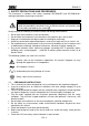
SIRIUS 87 1. SAFETY PRECAUTIONS AND PROCEDURES The instrument is conforms with safety standards IEC/EN61557 and IEC/EN61010-1 relating to electronic measuring instruments. CAUTION For your own safety as well as that of the apparatus you are recommended to follow the procedures described in this instruction manual and carefully read all the notes preceded by the symbol .
SIRIUS 87 1.2. DURING USE Carefully read the following recommendations and instructions: CAUTION No compliance with the CAUTIONs and/or Instructions may damage the apparatus and/or its components or injure the operator.
SIRIUS 87 2. GENERAL DESCRIPTION Dear Customer, we thank you for your patronage. The instrument you have just purchased will grant you accurate and reliable measurements provided that it is used according to the present manual’s instructions. The instrument was designed to grant the user the utmost safety conditions thanks to a new concept assuring double insulation and over voltage category III. 2.1.
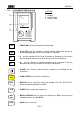
SIRIUS 87 2.2. INSTRUMENT DESCRIPTION CAPTION: 1 1. Display 2. Function keys 3. Rotary switch 2 FUNC Un/In DIST S UL 3 START STOP FUNC DISP CLR RCL ESC SAVE FUNCTION key to select one measuring mode. Un/In DIST Un/In DIST key for selection of rated voltage, differential current or distance depending on which measurement is selected. Ss S s key for selection of RCD type (Common or Selective) or to increase the test duration interval or to scroll the results of the stored tests.
SIRIUS 87 3. PREPARATION FOR USE 3.1. INITIAL CHECKS This instrument has been checked mechanically and electrically prior to shipment. Any care has been taken to ensure that the instrument reaches you under safe conditions. You are recommended, however, to carry our a rapid check to detect any possible damage which might have been caused during transport. Should this be the case, contact immediately your dialer. Check also that the packaging contains all the parts listed under § 9.3 .
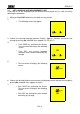
SIRIUS 87 3.5. SET LANGUAGE AND MEASUREMENT UNIT Is possible to set the language and the distance measurement unit (in earth resistivity) following this procedure: 1. While pushing FUNC button turn the switch on any position. 2. The following screen will appear. LA E 3. Choose the desired language between English, Spanish, German and Italian that change by pushing S▲ and UL▼ keys (appear En, ES, dE, IT). 4. Push SAVE key confirming the choice. The instrument will display the following screen.
SIRIUS 87 4. DESCRIPTION OF THE ROTARY SWITCH FUNCTIONS 4.1. LOW: CONTINUITY TEST OF EARTH CONDUCTORS WITH 200MA The measurement is performed with a test current higher than 200mA and open circuit voltage ranging from 4 to 24V DC according to IEC/EN 61557-2 and VDE 0413 part 4. CAUTION Before carrying out the continuity test make sure that there is no voltage at the ends of the conductor under test. Turn the switch on LOW position. Switch on the instrument.
SIRIUS 87 4.1.1. Mode "CAL" 1. Select mode CAL by means of the FUNC key. 2. Connect the black and blue cables to the instrument input terminals B1 and B4 respectively: Fig. 1 Connection of instrument terminals during calibration procedure 3. If the cables supplied with the instrument are not long enough for the measurement you can extend the blue cable. 4. Connect the crocodiles to the cable terminals. 5.
SIRIUS 87 CABLES USED FOR THE TEST Before each measurement always make sure that the calibration is referred to the cables in use. During a continuity test, if the resistance value free of calibration (that is the resistance value less the calibration offset value) is negative, the symbols as well as blinking CAL are displayed (according to 5th screen § 4.1.3).
SIRIUS 87 4.1.2. Continuity measurement mode "AUTO", "R+TIMER", "R-TIMER" 1. Select the desired mode by means of the FUNC key. 2. Connect the black and blue cables to the instrument input terminals B1 and B4 respectively Fig. 2 Connection of the instrument terminals during LOW test 3. If the cables supplied with the instrument are not long enough for the measurement you can extend the black cable. 4. Connect two crocodiles to the cable terminals. 5.
SIRIUS 87 4.1.2.1. Mode "AUTO" At the end of the test, if the average resistance value Ravg results to be lower than 5 the instrument emits a double sound signal indicating the positive outcome of the test and displays one screen similar to the screen alongside. CAL LOW 1.07 219 mA AUTO SAVE 4.1.2.2. SAVING: Average current Iavg. value test value The test can be stored pressing the SAVE key twice (according to § 5.1).
SIRIUS 87 4.1.3. Anomalous cases during "AUTO", "R+TIMER", "R-TIMER" tests In case a value of Ravg or R+ or Rhigher than or equal to 5 but lower than 99.9 was detected, at the end of the test the instrument emits a long sound signal and displays one screen similar to the screen alongside. ATTENTION: value of Ravg higher than 5 5.75 216 mA 5 s CAL LOW > 99.9 - - - mA CAL LOW > 99.9 - - - mA 4s ATTENTION: value of R+ or Ris too high.
SIRIUS 87 4.2. M: INSULATION RESISTANCE MEASUREMENT The measurement is performed according to IEC/EN61557-2 and VDE 0413 part 1. CAUTION Before effecting the insulation test make sure that the circuit under test is not energized and all the relative loads are disconnected. Turn the switch on M position. Switch on the instrument.
SIRIUS 87 4.2.1. Procedure to measure insulation resistance in any modes 1. Select the desired mode by means of the FUNC key. 2. Connect the black and blue cables to the instrument input terminals B1 and B4 respectively Fig. 3 Insulation P-PE with untied cables Fig. 4 Insulation P-PE with Shuko cable 3. If the cables supplied with the instrument are not long enough for the measurement you can extend the blue cable. 4.
SIRIUS 87 4.2.1.1. 6. Mode "MAN" START STOP Press the START/STOP key. The instrument effects the test lasting: Minimum 6 seconds in case the key is pressed and released within 5 seconds. Until the key is released for all the other cases.
SIRIUS 87 4.2.1.2. Mode "TIMER" 6. Use the following keys to set the duration time of the test: 7. S▲ Press this key to increase the duration time of the test (Tmax=999 seconds). UL▼ Press this key to decrease the duration time of the test (Tmin=10 seconds). START STOP Press the START/STOP key. The instrument effects the measurement ending when the set time has elapsed. 999 seconds Maximum value of the test duration. 10 seconds Minimum value of the test duration.
SIRIUS 87 4.2.2. Special cases which may occur during the tests "MAN", "AUTO", "TIMER" In case a value of RISO higher than RMAX was detected (depending on the selected voltage see following Note table, the instrument emits a double sound signal at the end of the test indicating the positive outcome of the test and displays one screen similar to the screen alongside.
SIRIUS 87 4.3. RCD RCD : TESTS ON RCDS TYPE A OR AC The test is effected according to IEC/EN61557-6, EN61008, EN61009, EN60947-2 B 4.2.4 and VDE 0413 part 6. CAUTION The automatic check of the RCD features causes the tripping of the RCD itself. Therefore check that there is no power or load connected downstream the RCD under test which could be affected by the installation switching off.
SIRIUS 87 Mode Ut (the instrument effects the test with a leakage current equal to half the value of the selected rated current and calculates the contact voltage as well as the Ra earth resistance with a leakage current in phase with the voltage or a leakage current phase shifted by 180° with respect to the voltage). Note: According to standard praxis it is recommended to effect RCD test both with phase 0° and with phase 180°. Therefore the test is to be repeated for both phase valves of test current.
SIRIUS 87 d) The instrument effects the test at In 180°. Follow the same procedure as described under c). e) The instrument effects the test at 5In 0°. Follow the same procedure as described under c). f) The instrument effects the test at 5In 180°. Follow the same procedure as described under c). The test is completed. In case of AUTO working mode the operator shall switch the RCD on whenever the instrument displays the blinking symbol “rcd” signaling the RCD tripping.
SIRIUS 87 4.3.1. Measurement procedure for RCD test valid for all the working modes 1. Select the desired mode by means of the FUNC key. 2. Connect the 3 black, blue and green connectors of the three-terminal shuko cable or of the single cables to the corresponding input terminals of the instrument B1, B3, B4 (see Fig. 5, Fig. 6, Fig. 7, Fig. 8). In case of using untied cables connect the crocodiles to the free ends of the cables. Fig. 5: Connection for RCD test on Single/Two phase system 230V Fig.
SIRIUS 87 4.3.1.1. Mode "MAN x½" 4. START STOP Press the START/STOP key once. The instrument carries out the test injecting a current in phase with positive half wave of the voltage indicated on display by 0°. Press the START/STOP key twice. The instrument carries out the test injecting a current in phase with negative half wave of the voltage indicated on display by 180°.
SIRIUS 87 4.3.1.2. Mode "MAN x1, x2, x5" 4. START STOP Press the START/STOP key once. The instrument carries out the test injecting a current in phase with positive half wave of the voltage indicated on display by 0°. Press the START/STOP key twice. The instrument carries out the test injecting a current in phase with negative half wave of the voltage indicated on display by 180°.
SIRIUS 87 4.3.1.3. Mode "AUTO" 4. START STOP Press the START/STOP key: The instrument carries out the following six tests with different values of rated current: 1/2In at 0° (the RCD shall not trip). 1/2In at 180° (the RCD shall not trip). In at 0° (the RCD trips, blinking rcd, switch it on again). In at 180° (the RCD trips, blinking rcd, switch it on again). 5In at 0° (the RCD trips, blinking rcd, switch it on again). 5In at 180° (the RCD trips, end of the test).
SIRIUS 87 4.3.1.4. Mode "RAMP 4. START STOP " Press the START/STOP key once. The instrument carries out the test injecting a current in phase with positive half wave of the voltage indicated on display by 0°. Press the START/STOP key once. The instrument carries out the test injecting a current in phase with negative half wave of the voltage indicated on display by 180°. The instrument generates a leakage current growing step by step for a given time interval.
SIRIUS 87 4.3.1.5. Mode "Ut" START 4. Press the START/STOP key once: the instrument carries out the test. STOP If the RCD does NOT trip the instrument emits a double sound signal indicating the positive outcome of the test and displays the screen alongside. Value of contact voltage Ut detected referred to the rated value of the RCD current set. RCD ~ 1.4 V OK 49 N30mA Ut 0° UL=50 V Value of earth resistance Ra. The display of the message "o.r.
SIRIUS 87 4.3.3. Anomalous cases which may occur during the RCD tests in any working mode Should the instrument detect that the phase and/or neutral cables are not connected to an installation, screen alongside is displayed when pressing START/STOP.
SIRIUS 87 If the instrument detects that the earth cable (green) is not connected, the screen alongside is displayed for 5 seconds then the initial display is back. Check the connections of PE conductor under test. RCD ~ >1999 PE no SAVE or RCD Message “no PE”: the instrument does not detect the protection circuit. THE PREVIOUS RESULT CANNOT BE SAVED.
SIRIUS 87 During the ramp test if the RCD trips to separate the circuit at a tripping current higher than In (Type AC) or 1.4 In (Type A with In>10mA) or 2 In (Type A with In10mA), the instrument emits a long sound signal at the end of the test and displays the values alongside. RCD ~ 33 mA 58ms or RCD RCD tripping time 1V t 0° UL= 50V ATTENTION: the RCD tripping current is higher than the rated value of the set differential current (IN=30mA was set in the example).
SIRIUS 87 In case the instrument is unable to generate the current because the fault loop presents a too high resistance, the instrument emits a long sound signal at the end of the test and displays the values alongside.
SIRIUS 87 4.4. LOOP : LOOP IMPEDANCE, SEQUENCE TEST Turn the switch on LOOP FAULT CURRENT AND PHASE position. Switch on the instrument. FUNC The key FUNC permits to select one of the following measuring modes (which can be shown cyclically when pressing the key): Mode “P-N” (the instrument measures the resistance between the phase and neutral conductors and calculates the phase to neutral prospective short circuit current).
SIRIUS 87 4.4.1. High resolution Impedance measurement (0.1m) SIRIUS 87 is connectable to an external optional accessory (IMP57) useful for high resolution impedance measurement close to a power transformer. The high Resolution impedance measurement is available inside the LOOP P-P, P-N, P-PE modes by mean Un/IΔn key.
SIRIUS 87 4. Connect the shuko plug into a 230V 50Hz socket or the crocodiles to the conductors of the three-phase system (see see Fig. 9, Fig. 10). 5. START STOP Press the START/STOP key. The instrument starts the test. At the end of the test the instrument emits a double sound signal indicating that the test is correctly terminated and displays the values alongside. LOOP 1.
SIRIUS 87 4.4.3. Mode "P-P" 1. Select P-P mode by means of the FUNC key. 2. If possible disconnect all low impedance loads downstream the point at which the measurement is to be taken, as such an impedance would be in parallel with the line impedance to be measured. 3. Connect the 3 black, green and blue connectors of the single cables in the corresponding input terminals of the instrument B1, B3, B4 (see possible connections in the following pictures).
SIRIUS 87 4.4.4. Mode "P-PE" 1. Select P-PE mode by means of the FUNC key. 2. Connect the 3 black, blue and green connectors of the three-terminal shuko cable or of the single cables in the corresponding input terminals of the instrument B1, B3, B4 (see Fig. 12, Fig. 13, Fig. 14). When using untied cables connect the crocodiles to the free ends of the cables. Fig. 12: Connection for P-PE impedance measurement Single/Two phase 230V Fig.
SIRIUS 87 5. START STOP Press the START/STOP key once. The instrument carries out the test injecting a current in phase with positive half wave of the voltage indicated on display by 0°. Press the START/STOP key twice. The instrument carries out the test injecting a current in phase with negative half wave of the voltage indicated on display by 180°. At the end of the test the instrument emits a double sound signal indicating that the test is correctly terminated and displays the values alongside.
SIRIUS 87 4.4.5. Mode " " 1. Connect the three black, red and green connectors of the untied cables in the corresponding input terminals of the instrument B1, B2, B3 and the crocodiles to the free ends of the cables. Fig. 15: Instrument connection for phase sequence indication 2. Connect the crocodiles to the three phases of the system under test. The instrument displays the following screen (before pushing START/STOP key): Voltage value between Phase1 and Phase2.
SIRIUS 87 4.4.6. Anomalous cases which may occur during LOOP tests in any working mode Should the instrument detect that the phase and/or neutral cables are not connected to an installation, screen alongside is displayed when pressing START/STOP. This screen is displayed when system the phase conductor was reversed with respect to the neutral. LOOP P-N VOL Message "no VOL tAG”: a too low voltage was detected. AG LOOP Message “Att”: too low voltage between phase and earth.
SIRIUS 87 If the instrument detects that the earth cable (green) is not connected, the screen alongside is displayed for 5 seconds then the initial display is back. Check the connections of PE conductor under test. LOOP >1999 PE no If a contact voltage Ut higher than the selected limit (UL) is detected the instrument interrupts the test and emits a long sound signal at the end of the test and displays the values alongside.displays the screen alongside.
SIRIUS 87 If the instrument finds a network frequency out of range it does not permit to effect the tests and displays the message alongside. LOOP Message “Err SYn cro”: frequency is out of range. c SAVE THIS RESULT CANNOT BE SAVED. If under P-PE mode the instrument carries out the test and detects a resistance to higher than 1999, the screen alongside is displayed.
SIRIUS 87 4.4.7. Anomalous cases which may occur during phase sequence tests In case that every delta voltages result to be lower than 100V, the instrument does not effect the test and displays the screen alongside. Messagge “Lo VOL tAG”: the instrument has at least one too low voltage. The instrument does not effect the test. If the voltage present at B1 input too low, when START/STOP is pressed the instrument displays the message alongside.
SIRIUS 87 If one cable is not connected to the network or one phase is absent, the instrument displays the screen alongside Black cable=L1 is not connected to one phase of the installation. Voltage between phase L3 and phase L1 is null (L3 - L1). 0V 0 V 388 V Black cable= L1 is not connected to one phase of the installation. Voltage between phase L2 and phase L3 is not null (L2- L3). Black cable=L1 is not connected to one phase of the installation.
SIRIUS 87 4.5. Ra15mA : GLOBAL EARTH RESISTANCE MEASUREMENT Turn the switch on Ra15mA position. Switch on the instrument. 1. Connect the three black, blue and green connectors of the shuko cable or of the untied cables in the corresponding input terminals of the instrument B1, B3, B4 (see Fig. 16, Fig. 17, Fig. 18). When using untied cables connect the crocodiles to the free ends of the cables. Fig. 16: Connection for Ra measurement Single/Two phase 230V Fig.
SIRIUS 87 3. UL▼ 4. START STOP The key ULt permits to select one of the following limit values for the contact voltage (which can be shown cyclically when pressing the key): 50V (default) 25V. Press the START/STOP key. The instrument starts the test. At the end of the test the instrument emits a double sound signal indicating that the test is correctly terminated and displays the values alongside.
SIRIUS 87 4.5.1. Anomalous cases which may occur during RA15mA Should the instrument detect that the phase and/or neutral cables are not connected to an installation, screen alongside is displayed when pressing START/STOP. Message "no": the instrument does not effect the test because a too low voltage was detected.
SIRIUS 87 If the instrument detects that the earth cable (green) is not connected, the screen alongside is displayed for 5 seconds then the initial display is back. Check the connections of PE conductor under test. >1999 RCD LOOP > 50 A Message "no PE": the instrument does not detect the protection circuit.
SIRIUS 87 If under P-PE mode the instrument caries out the test and detects a global earth resistance to higher than 1999, the screen alongside is displayed for 5 seconds then the initial display is back. Value of contact voltage Ut detected referred to the carried out value of the RCD current set. Resolution 1V. SAVE SAVING: RCD LOOP >1999 P-PE 31 V Message ">1999": the instrument detects an earth resistance higher than 1999.
SIRIUS 87 4.6. EARTH : EARTH RESISTANCE AND SOIL RESISTIVITY MEASUREMENT Turn the switch on EARTH position. Switch on the instrument. FUNC The key FUNC permits to select one of the following measuring modes (which can be shown cyclically when pressing the key): Mode “2P” (the instrument measures earth resistance between 2 points). Mode “3P” (the instrument measures earth resistance using two auxiliary earth rods). Mode ““ (the instrument measures earth resistivity).
SIRIUS 87 4.6.1. Measurement procedure for "2P" test mode 1. Select "2P" earth measurement mode by means of the F1 key. 2. Connect the Black, Red, Green and Blue cables to the corresponding input terminals of the instrument B1, B2, B3, B4 (see Fig. 19) 3. Connect the black, and green cables to the earth plant and red and blue cables to the auxiliary rod. Fig. 19: 2 points earth resistance measurement 4. START STOP Press the START/STOP key. The instrument starts the test.
SIRIUS 87 When the environmental conditions preclude the “3P” measurement mode, as for example in the city center, In TT plants is possible to measure the earth resistance with the simplified “2P” method that gives an higher value than the “3P” mode does. An auxiliary rod is necessary, it must have an unimportant earth resistance and must be independent by the earth plant under test. In the picture is shown a water tube as auxiliary rod, but it could be replaced by any metallic object fixed to the ground.
SIRIUS 87 4.6.1.1. Earth resistance measurement from a socket On TT installations it’s possible to take an earth measurement with a simplified method, which gives an excess value (therefore safer), using the NEUTRAL of the national Energy Board taken directly from a socket as an auxiliary rod; if also the earth connection is available, naturally the measurement can be taken on the socket directly, between NEUTRAL and EARTH.
SIRIUS 87 4.6.2. Measurement procedure for "3P" test mode The measurement is taken according to what prescribed for VDE 0413, IEC/EN61557-5. 1. Select "3P" earth measurement mode by means of the F1 key. 2. Connect the Black, Red, Green and Blue cables to the corresponding input terminals of the instrument B1, B2, B3, B4 (see Fig. 21). 3. Connect the black, and green cables to the earth plant and red and blue cables to the auxiliary rods. Fig.
SIRIUS 87 Note: If START/STOP key was kept pressed, the instrument takes more consecutive tests. 5. When a new value is acquired the instrument emits a short sound and calculates the new average value. 6. DISP Press DISP key to show how many measurements are in average value calculation and the measuring mode. 7. CLR Press CLR key if you want to cancel the medium value of the resistance and the no. of measurements which are included in the calculation.
SIRIUS 87 4.6.3. Measurement procedure for "" test mode The earth resistivity is a very useful parameter, its value could help the designer to correctly size the earth rods in an earth plant. The measurement is taken according to what prescribed for VDE 0413, IEC/EN61557-5 1. Select "" earth measurement mode by means of the F1 key. 2. Connect the Black, Red, Green and Blue cables to the corresponding input terminals of the instrument B1, B2, B3, B4 (see possible connections in the following picture). 3.
SIRIUS 87 At the end of the test the instrument displays the values alongside. Earth resistivity value 36.5 2 m 0.93 CAUTION The display of “Measuring” means that the instrument is measuring. During this phase never disconnect test leads. SAVE Note: SAVING: The tests can be stored pressing the SAVE key twice (according to § 5.1). If START/STOP key was kept pressed, the instrument takes more consecutive tests. 8.
SIRIUS 87 4.6.4. Anomalous cases which may occur during EARTH tests If the voltmetric circuit (red and green cables) is interrupted, when pressing START/STOP the instrument doesn’t manage to read the minimum voltage, therefore a screen similar to the one beside appears. Make sure that the terminals are connected correctly and that the voltmetric rod (red conductor) has not been driven into a gravely or scarcely conductive ground. If necessary, pour water around the rod.
SIRIUS 87 If the instrument measures an interfering voltage higher than 30V on the amperometric circuit, it doesn’t perform the test and a screen similar to the one beside appears. 31 V VOL AG Voltage value on the amperometric circuit SAVE THE PREVIOUS RESULT CANNOT BE SAVED. If the resistance measured is higher than the full scale of the instrument, when pressing START/STOP the instrument performs the test and a screen similar to the one beside appears.
SIRIUS 87 5. OPERATION WITH MEMORY 5.1. SAVING RESULTS If the results relative to the tests effected are to be stored you can proceed as follows: 1. SAVE Press the SAVE key once. If the memory of the instrument is not empty it displays the screen alongside. Number of the memory location in which the measurement results will be stored. Value of the parameter PLA related to the measurement to be saved. MEM 3 Pla 02 UL▼ 2.
SIRIUS 87 5.2. RECALL RESULT AT DISPLAY If you want to recall the stored test results proceed as follows: 1. RCL ESC Press the RCL/ESC key. If the memory of the instrument is not empty it displays the screen alongside. Number of the memory location in which the measurement results were stored. Value of the parameter PLA related to the saved measurement MEM 3 Pla 02 UL▼ 2. S▲ 3. DISP Use the UL▼, S▲ keys to select the memory location number to be displayed.
SIRIUS 87 5.3. CLEAR MEMORY If you want to cancel the stored tests results proceed as follows: 1. RCL ESC Press the RCL/ESC key. The instrument displays a screen like the following: Number of the memory location in which the measurement results were stored. Value of the parameter PLA related to the saved measurement. MEM 3 Pla 02 UL▼ Use the UL▼, S▲keys to select the number of the memory location. 2.
SIRIUS 87 6. RESET OF THE INSTRUMENT BEFORE OF A RESET PROCEDURE DOWNLOAD THE STORED TESTS ON A PC 6.1. RESET PROCEDURE 1. Press at the same time the keys DISP, CLR, RCL and then ignite the instrument. 2. The screen nearby is displayed for 5 seconds, after which the instrument emits a sound signal and then displays the screen relative to the function selected with the rotary switch.
SIRIUS 87 7. INSTRUMENT CONNECTION TO A PC The connection between PC and instrument is realized through the serial port and optical serial cable, provided with the software package. Before effecting the connection it is necessary to select the COM port used for the transmission. To set this parameter start the software and look up the help on line. ATTENTION: The selected port shall NOT be shared by other devices or applications (example mouse, modem, etc.)..
SIRIUS 87 8. MAINTENANCE 8.1. GENERAL 1. The tester you have purchased is a precision instrument. Strictly follow the instructions for use and storage reported in this manual to avoid any possible damage or danger during use. 2. Do not use this tester under unfavorable conditions of high temperature or humidity. Do not expose to direct sunlight. 3. Be sure to turn off the tester after use.
SIRIUS 87 9. TECHNICAL SPECIFICATIONS 9.1. TECHNICAL FEATURES Accuracy is indicated as [% reading + (number of digits) * resolution]. It refers to the atmospheric conditions listed in § 9.2.1.
SIRIUS 87 - Tripping time (tN) Measuring range (ms) ½ IN, IN 1999 1200 general 2 IN 1250 selective 150 general 5 IN RCD (*) 1160 selective Resolution (ms) Accuracy 1 (2% rdg + 2 dgt) (*) ”Man 5 In” and “AUTO” test modes aren’t available for RCD type A 500mA - Earth resistance RA without RCD tripping Measuring range () 1 1999 Test current Accuracy -0%, +(5% rdg + 3 dgt) Resolution () 1 0.
SIRIUS 87 - Global earth resistance (Ra15mA) Measuring range () 1 1999 Test current Phase to earth test voltage Resolution () 1 Accuracy (5% rdg + 3 dgt) 15mA 100 265V 50Hz 0,5Hz - Earth resistance measurement with voltamperometric method Measuring range () 0,01 19,99 20,0 199,9 200 1999 Test current Open load test voltage Resolution () 0,01 0,1 1 Accuracy (5% rdg + 3 dgt) <10mA 77,5Hz <20V RMS - Earth resistivity measurement Measuring range () 0.06 19,99 m 20.0 199.
SIRIUS 87 9.2. ENVIRONMENT 9.2.1. Environmental working conditions Reference temperature: 23° ± 5°C (73°F ± 41°F) Working temperature: 0°C ÷ 40 °C (32°F ÷ 104°F) Relative humidity allowed: <80%RH Storage temperature: -10 ÷ 60 °C (14°F ÷ 140°F) Storage humidity: <80%RH This instrument satisfies the requirements of Low Voltage Directive 2006/95/EC (LVD) and of EMC Directive 2004/108/EC 9.3. ACCESSORIES 9.3.1.
SIRIUS 87 10. SERVICE 10.1. WARRANTY CONDITIONS This instrument is guaranteed against any defect in material and manufacturing in compliance with the general sales terms and conditions. Throughout the period of guarantee all defective parts may be replaced and the manufacturer reserves the right to repair or replace the product. If the instrument is to be returned to the after-sales service or to a dealer transportation costs are on the customer’s behalf. Shipment shall be however agreed upon.
SIRIUS 87 11. APPENDIX 11.1. LOW: CONTINUITY MEASUREMENT ON PROTECTIVE CONDUCTORS Purpose of the test is to check the continuity of: a) protective conductors (PE), main equalizing potential conductors (EQP), secondary equalizing potential conductors (EQS) in TT and TN-S systems. b) neutral conductors having functions of protective conductors (PEN) in TN-C system.
SIRIUS 87 ALLOWABLE VALUES The guidelines do not give any indication on the maximum resistance values which cannot be overcome, in order to be able to declare the positive outcome of the continuity test. The guidelines IEC/EN61557-1 simply requires that the instrument in use warns the operator if the test was not carried out with a current of at least 0.2 A and an open circuit voltage ranging from 4 V to 24 V.
SIRIUS 87 EXAMPLE OF INSULATION MEASUREMENT ON AN INSTALLATION SWITCH A SWITCH B SWITCH C OPEN OPEN OPEN OPEN OPEN SWITCH D SWITCH E Insulation measurements on an installation.
SIRIUS 87 Switch situation 1 Point under test Measurement result Turn the switch Effect the measurement If R RLIMIT A, l D and E off on switch A If R RLIMIT If R RLIMIT 2 Turn the switch Effect the measurement B off on switch A If R RLIMIT If R RLIMIT Effect the measurement on switch B If R RLIMIT 3 If R RLIMIT 4 Turn the switch Effect the measurement C off on switch B If R RLIMIT If R RLIMIT Effect the measurement on switch C If R RLIMIT 5 Judgment on the installation OK (end o
SIRIUS 87 11.3. CHECK OF CIRCUIT SEPARATION PURPOSE OF THE TEST Purpose of the test is to be effected in case the protection is realized through separation ( SELV or PELV or electrical separation), shall check that the insulation resistance measured according to the indications below (depending on the separation type) complies with the limits reported in the table relative to the insulation measurements.
SIRIUS 87 EXAMPLE OF CHECKING THE SEPARATION AMONG ELECTRICAL CIRCUITS Insulation or safety transformer making the separation among the circuits. TEST AMONG THE ACTIVE PARTS Connect a test lead of the instrument to one of the two conductors of the separate circuit and the other to one of the conductors of a no separate circuit. Between active parts of the separated circuit... ...
SIRIUS 87 11.4. WORKING TEST OF RCDS (RCD, RCD/DC, RCD S, RCD/DC S) Purpose of the test is to check if general and selective RCDs have been installed and adjusted properly and whether they maintain their features over the time.
SIRIUS 87 Among the test results of the RCD tripping time also the earth resistance value Ra is displayed in , this value for the TN and IT systems is not to be considered while for the TT systems it is merely indicative. 11.5. TEST OF RCD TRIPPING TIME (RCD, RCD/DC) Purpose of the test is to check the real tripping time of the general RCDs (it does not apply to the selective RCDs).
SIRIUS 87 11.6. MEASUREMENT OF SHORT CIRCUIT FAULT IMPEDANCE (ZPN, ZPP) Purpose of the test is to check that the tripping power of the RCD is higher than the maximum fault current of the installation. INSTALLATION PARTS TO BE CHECKED The test shall be effected in the point where the short circuit current is the highest possible, usually immediately downstream the RCD to be checked.
SIRIUS 87 11.8. EARTH RESISTANCE MEASUREMENT IN TT SYSTEMS Purpose of the test is to check that the RCD is coordinated with the earth resistance value. It is not possible to assume an earth resistance value as reference limit when controlling the test result, while it is necessary to check every time that the co-ordination complies with the requirements of the standards. INSTALLATION PARTS TO BE CHECKED The earth installation under working conditions.
SIRIUS 87 11.9. EARTH RESISTANCE MEASUREMENT, VOLTAMPEROMETRIC METHOD Method for small earth plant Let a current circulate between the earth rod and a current probe positioned at a distance from the earth equipment outline corresponding to fivefold the diagonal of the area delimiting the earth equipment. Position the voltage probe at half-way between the earth rod and the current probe, then measure the voltage between the two.
SIRIUS 87 11.10. EARTH RESISTIVITY MEASUREMENT Purpose of the test is to measure the resistivity value of the ground in order to define the type of rods to be used. EQUIPMENT PARTS TO BE TESTED For the resistivity test admissible values do not exist. The various values measured by positioning the rods at growing distances “a” must be quoted in a graph. According to the resulting curve, suitable rods will be chosen.
Specific resistivity of the ground E (m) SIRIUS 87 Curve 1: as decreases only in depth, it’s possible to use only a rod in depth. 1 Curve 2: as decreases only until the depth A, it’s not useful to increase the depth of the rod beyond A. 2 3 Curve 3: even at a superior depth, does not decrease, therefore a ring rod must be used. Distance between the rods a(m) APPROXIMATE EVALUATION OF INTENTIONAL RODS CONTRIBUTION (64-12 2.4.
NOTE ________________________________________________________________________ ________________________________________________________________________ ________________________________________________________________________ ________________________________________________________________________ ________________________________________________________________________ ________________________________________________________________________ _____________________________________________________________________
YAMUS0024HT0 Via della Boaria 40 48018 – Faenza (RA)- Italy Tel: +39-0546-621002 (4 linee r.a.) Fax: +39-0546-621144 email: ht@htitalia.it http://www.ht-instruments.