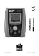
User manual PVCHECK Copyright HT ITALIA 2013 Release EN 1.
PVCHECK Table of contents: 1. PRECAUTIONS AND SAFETY MEASURES ............................................................... 3 1.1. 1.2. 1.3. 1.4. 2. GENERAL DESCRIPTION ........................................................................................... 5 2.1. 2.2. 3. Initial checks ...................................................................................................................... 6 Instrument power supply ......................................................................
PVCHECK 6.5.2. 6.5.3. 6.5.3.1. 6.6. 7. Anomalous situations ....................................................................................................................... 49 List of display messages ................................................................................................. 50 STORING DATA ......................................................................................................... 51 7.1. 7.2. 7.3. Saving efficiency measures..................................
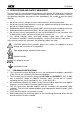
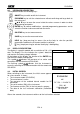
PVCHECK 1. PRECAUTIONS AND SAFETY MEASURES The instrument has been designed in compliance with directive IEC/EN61010-1 relevant to electronic measuring instruments. Before and while carrying out measurements, observe the following indications and read all notes preceded by the symbol with the utmost attention.
PVCHECK 1.2. DURING USE Please carefully read the following recommendations and instructions: CAUTION Failure to comply with the caution notes and/or instructions may damage the instrument and/or its components or be a source of danger for the operator. The symbol “ ” indicates a full charge level of the internal batteries. When battery charge decreases to a minimum level, the symbol “ ” appears on the display.
PVCHECK 2. GENERAL DESCRIPTION 2.1. INTRODUCTION This instrument has been designed to carry quick checks (IVCK) on photovoltaic modules/strings in order to verify the parameters declared by the manufacturer. In addition, this instrument measures insulation/continuity on PV modules/strings/fields and evaluates the efficiency of a PV field. IVCK and insulation/continuity measurements may be performed in sequential order IVCK Insulation Continuity, or be carried out separately in manual mode. 2.2.
PVCHECK 3. PREPARATION FOR USE 3.1. INITIAL CHECKS Before shipping, the instrument has been checked from an electric as well as mechanical point of view. All possible precautions have been taken so that the instrument is delivered undamaged. However, we recommend checking it to detect any damage possibly suffered during transport. In case anomalies are found, immediately contact the Dealer. We also recommend checking that the packaging contains all components indicated in § 10.7.
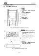
PVCHECK 4. NOMENCLATURE 4.1. INSTRUMENT DESCRIPTION CAPTION: 1. Inputs 2. Display 3. Connector for optical output/USB port 4. Arrow keys/ENTER key 5. GO/STOP key 6. SAVE key 7. ON/OFF key 8. HELP / key 9. ESC/MENU key Fig. 1: Description of the front part of the instrument CAPTION: 1. Input for irradiation measuring probe 2. Input for auxiliary temperature measuring probe / DC current clamp (IVCK, EFF) 3. P, N inputs for DC voltage (IVCK, EFF) / Insulation (M) measurement 4.
PVCHECK 4.2. KEYBOARD DESCRIPTION The keyboard includes the following keys: ON/OFF key to switch on/off the instrument ESC/MENU key to exit the selected menu without confirming and to go back to the main menu keys to move the cursor inside the various screens in order to select programming parameters ENTER key to confirm modifications, selected programming parameters and to select the function to be accessed from the menu.
PVCHECK 5. GENERAL MENU Pressing the ESC/MENU key in any condition of the instrument displays the general menu screen, in which the instrument may be set, the saved measures can be displayed and the desired measuring function may be selected. Use the cursor to select one of the options and confirm with ENTER to access the desired function. 15/05/12 15:34:26 IVCK Test mod.
PVCHECK 5.1.2. Measuring unit This section allows setting the measuring units of some parameters included in the database (DB) for the management of PV modules (see § 5.6) when measuring IVCK. 1. Position the cursor onto “Measuring Unit” by using the arrow keys (,) and confirm with ENTER. 2.
PVCHECK 5.1.4. Remote unit/Pyranometer This section allows selecting the type of remote unit to be used (if available) and setting the values of typical parameters (Sensitivity and Alpha) of the reference irradiance cell supplied with the instrument. The values of these parameters, which are printed on the back label of the cell, depend on the type of PV module being tested. 1. Position the cursor onto Remote Unit-Pyranometer by 15/05/12 15:34:26 using the arrow keys (,) and confirm with ENTER.
PVCHECK 5.1.5. Irradiance This section allows setting the minimum irradiance threshold both for IVCK measurement and for efficiency test on a PV installation. 1. Position the cursor onto “Irradiance” by using the arrow 15/05/12 15:34:26 keys (,) and confirm with ENTER. Min IrrIVCK :000W/m2 2.
PVCHECK 5.2. EFF – EFFICIENCY TEST SETTINGS FOR PV INSTALLATIONS The purpose of this measurement is to evaluate the DC efficiency of a photovoltaic installation, with the possibility of obtaining a positive or negative result of the check/recording depending on a limit on the nDC parameter, freely set by the user. For this test, the use of the optional remote unit SOLAR-02 is necessary (see § 6.1) 5.2.1. Instrument settings 1.
PVCHECK 5.2.2. System parameters 1. Position the cursor onto EFF by using the arrow keys 15/05/12 15:34:26 (,) and confirm with ENTER. The display shows the I r r - - values of the output electrical parameters of the P n o m 3.500 Tc - - photovoltaic generator. Te - - Pdc Vdc Idc ndc 0.0 0.000 0.0 - - - W/m2 kW °C °C kW V A GO to Start Selection EFF 2. Press the ENTER key. The instrument shows the 15/05/12 15:34:26 following options: System parameters and Instrument I r r - - Pnom 3.
PVCHECK 5.2.3. Selection of the compensation relationship of temperature effects This option allows selecting the relationship to be used to correct the measurements performed according to the modules’ temperature as regards the calculation of nDC efficiency. The following modes are available: - T.Mod.: Correction factor Rfv2 related to PV module Temp. (Italian guideline CEI-82-25) - T.Env: Correction factor Rfv2 related to environmental Temp.
PVCHECK 5.3. LOW – SETTINGS FOR CONTINUITY TEST WITH 200MA The purpose of this measurement is to test the continuity of protective conductors and equipotential ones (e.g. from rod to earth and connected foreign earth) and earth rods of SPDs on PV installations. The test must be carried out using a test current > 200mA according to the prescriptions of IEC/EN62446 guideline 5.3.1. Instrument settings 1. Position the cursor onto LOW by using the arrow keys 15/05/12 15:34:26 (,) and confirm with ENTER.
PVCHECK 5.4. M – SETTINGS FOR INSULATION MEASUREMENT 5.4.1. Instrument settings 1. Position the cursor onto M by using the arrow keys 15/05/12 15:34:26 (,) and confirm with ENTER. The display shows the I n s . T e s t : 1000 Ri min : 1.0 following screen: Mode : Vtest V M Field - - - V - - - V Ri(+) - - - M Ri(-) - - - M Rp - - - M M Selection 2. Press the ENTER key. The instrument shows the option: 15/05/12 15:34:26 Settings: Ins. Test : 1000 : 1.0 3. Confirm with ENTER.
PVCHECK 5.5.
PVCHECK modules’ Voc. “Manual” setting, made by the operator, of the known temperature value of the module in the line below. Aux temperature measurement with auxiliary probe PT1000. Tol. Voc (%) percentage value of the desired limit tolerance (set by the operator according to his/her own requirements) for the measurement of Voc carried out by the instrument. Allowable values: 0% 25%. The value between brackets (4%) indicates the reading error of the instrument in Voc measurement. Tol.
PVCHECK 5.6. DB – DATABASE MODULE MANAGEMENT The meter allows managing up to a maximum of 30 different types of PV modules, further to a DEFAULT module (not editable and not erasable) which can be used as reference case when no piece of information about the type of module being tested is available. The parameters, referred to 1 module, which can be set are described below in Table 1 together with their measuring range, resolution and validity condition. Symbol Description Range Resol.
PVCHECK 5.6.1. How to define a new PV module 1. Position the cursor onto DB by using the arrow keys (,) and confirm with ENTER. The display shows the screen which contains: The type of PV module The values of the parameters associated to the module (see Table 1) 2. Use the arrow keys ( , ) to select the “DEFAULT” module type and confirm with ENTER. 15/05/12 15:34:26 Model :DEFAULT Pmax Voc Vmpp Isc Impp Toll = = = = = = 185 44.5 37.5 5.40 4.95 0 Selection 3.
PVCHECK 5.6.2. How to modify an existing PV module 1. Select the PV module to be modified from the internal database by means of the arrow keys ( , ). 2. Press the ENTER key and select the “Modify” command using the arrow key (). 3. Confirm selection with ENTER. 4. By using the internal virtual keyboard it is possible to define again the name of the module or leave it unchanged by means of the arrow keys (,, , ). Press ENTER to digit any character of the desired name. 5.
PVCHECK 6. OPERATING INSTRUCTIONS 6.1. MEASURING EFFICIENCY PV PLANTS BY USING REMOTE UNIT SOLAR-02 For the sake of simplicity, further in this section, the word “string” will be used, although often the term “photovoltaic field” would be more correct. From the point of view of the instrument, the management of a single string or of more parallel strings (PV field) is identical.
PVCHECK 4. In order to guarantee the operator’s safety, disable the system being measured by means of the switches/breakers upstream and downstream of the DC/AC converter (inverter). 5. Bring PVCHECK and SOLAR-02 nearer (maximum distance of 1m between them). All instruments must be switched on (see the User Manual of SOLAR-2 for further details). 6. On PVCHECK, press the MENU key, select the function EFF and press ENTER; wait for the two units to start communicating with each other.
PVCHECK 15. Upon reaching “00” after pressing the GO/STOP key, the 15/05/12 15:35:00 test is started and the two units are synchronized with I r r - - each other. In these conditions the message “Recording P n o m 3.500 45 running…” is displayed on the main unit and TT ce 30 “Recording…” is displayed by SOLAR-02. Pdc 3.125 Vdc Idc ndc 389 8.01 - - - W/m2 kW °C °C kW V A Recording running… Selection EFF 16.
PVCHECK 28. After the automatic data transfer phase, the instrument will 15/05/12 15:35:00 display: Irr 712 W/m2 Do not show any results if do not exist on the PV P n o m 3 . 5 0 0 kW T c 4 5 °C installation a “stable irradiance” condition more than Te 30 °C the minimum irradiance threshold Pdc 3.125 kW dc 389 V Display the best performance values if during the V Idc 8.01 A recording, the Irradiance values reached the “stable” n d c 0.
PVCHECK 6.2. MEASURING PARAMETERS ON PV PLANT WITHOUT USING SOLAR-02 The “PV installation efficiency” test carried out without using the optional remote unit SOLAR-02 only allows evaluating output electrical parameters of a string or a photovoltaic field (quantities, Vdc, Idc and Pdc), which can be periodically recorded with a programmable integration period (see § 5.2.1). In this mode, the values of Irradiation, Te, Tc, the nDC efficiency value are not evaluated and no result is provided by the instrument.
PVCHECK 5. Connect the DC current clamp to the positive output conductor of the string, respecting the direction of the arrow found on the clamp itself as indicated in Fig. 5. Position the clamp so that the jaw is not near the negative conductor. 6. The display shows the first screen which contains the 15/05/12 15:34:26 values of the output electrical parameters of the I r r - - module/string. Pnom 3.500 Tc Te Pdc Vdc Idc ndc Selection - - - - 3.125 389 8.01 - - - Go to Start EFF 7.
PVCHECK 6.3. QUICK CHECK ON PV MODULES AND STRINGS (IVCK) 6.3.1. Foreword This function carries out a series of quick tests on a PV module/string, measuring in a sequence: The Voc voltage and the short-circuit current Isc according to the prescriptions of standard IEC/EN62446 with the possibility of measuring (by using the relevant probes) also the irradiance and module temperature values. Insulation resistance measurement (if enabled – see § 5.5.1), only carried out in STRING mode (see § 6.4.4) i.e.
PVCHECK 6.3.2. Carrying out an IVCK quick test without measuring irradiance CAUTION The maximum voltage between inputs P, N, E and C is 1000VDC. Do not measure voltages exceeding the limits given in this manual Do not perform test on PV modules or strings connected to the DC/AC converter The maximum current which can be measured by the instrument is 10A.
PVCHECK CAPTION: E: C: P: N: Green cable Blue cable Red cable Black cable 1. PV module/string 2. Main system earthing 3. Earthed metal structure in the system Fig. 6: Connection for IVCK test without irradiance measurement CAUTION Upon pressing the GO/STOP key, different error messages can be displayed by the instrument (see § 6.6) and, therefore, the test cannot be started. Check and eliminate, if possible, the problem causing the error message before going on with the test. 9.
PVCHECK 13.With continuity measurement selected, the instrument 15/05/12 15:34:26 odule : SUNPWR318 goes on by opening the short-circuit and carrying out the M Vdc : 548.0 V test between terminals E and C. Irr : 0 W/m2 14.The value of resistance in the continuity test is shown in T c : Auto °C field “Rpe” and the message “OK” appears in case the V o c , I s c : OK result of the test is positive (measured value lower than Ri(1000V) 116 M OK the maximum limit value set on the instrument). 2.00 15.
PVCHECK 6.3.3. Carrying out an IVCK quick test and measuring irradiance CAUTION The maximum voltage between inputs P, N, E and C is 1000VDC. Do not measure voltages exceeding the limits given in this manual. Do not perform test on PV modules or strings connected to the DC/AC converter The maximum current which can be measured by the instrument is 10A.
PVCHECK cell until it rests on the tang found on the bracket so that the cell is perfectly parallel to the surface of the module, then fix it with the relevant screws provided. Fig. 7: Positioning the inclinometer M304 11. Connect the output of the cell corresponding to the type of module being tested to the IRR. input of the instrument using the cable supplied with the cell, or to the PYRA/CELL input of the remote unit SOLAR-02, if used (see Fig. 8 and Fig. 9) 12.
PVCHECK Fig. 8: Connection for IVCK test with direct irradiance measurement CAPTION: E: C: P: N: Green cable Blue cable Red cable Black cable 1. PV module/string 2. Main system earthing 3. Earthed metal structure in the system 4. Reference cell for irradiance measurement 5. Temperature sensor (if required) 6. Unità remota SOLAR02Remote unit SOLAR-02 Fig. 9: Connection for IVCK test with irradiance measurement through SOLAR-02 14.
PVCHECK 16.When Voc and Isc measurements are complete, the 15/05/12 15:34:26 odule : SUNPWR318 message “OK” is shown in case the result of the test is M Vdc : 548.0 V positive (measured values within the tolerances set on the I r r : 856 W/m2 instrument) Tc : Auto °C 17.
PVCHECK o OK: if all results under STC are OK, o NO if one of the results under STC is NO 23.Press the key to go back to the previous screen. 24.Press the SAVE key to store the test result in the instrument’s memory (see § 7.2) or the ESC/MENU key to exit the screen without saving and go back to the main measuring screen. CAUTION The average values of Voc and Isc are displayed in the results’ page.
PVCHECK 6.3.4.1. Anomalous situations when performing IVCK tests 1. In case the instrument detects a voltage higher than 15/05/12 15:34:26 odule : SUNPWR318 1000V at terminals P-N, P-E and N-E, it does not carry M Vdc : 0.0 V out the test, gives out a long sound and displays the I r r : 0 W/m2 Tc : Auto °C message “Vin > 1000”. Voc,Isc: Ri(1000V) - - - M Rpe (Cal) - - - Vin > 1000 IVCK Selection 2.
PVCHECK 6.4. MEASUREMENT OF INSULATION ON PV MODULES/STRINGS/FIELDS (M) 6.4.1. Foreword The purpose of this function is to measure the insulation resistance of the active conductors of a module, string, of a whole PV field and of possible unearthed metal masses according to the prescriptions IEC/EN62446 guideline.
PVCHECK CAPTION: E: P: N: Green cable Red cable Black cable 1. Unearthed PV field 2. Main system earthing Fig. 10: Instrument connection for insulation measurement in FIELD mode CAUTION Upon pressing the GO/STOP key, different error messages can be displayed by the instrument (see § 6.6) and, therefore, the test cannot be started. Check and eliminate, if possible, the problem causing the error message before going on with the test. 4. Press GO/STOP to start the test.
PVCHECK 6.4.3. Measuring insulation – TIMER mode 1. Position the cursor onto M by using the arrow keys 15/05/12 15:34:26 (,) and confirm with ENTER. The display shows the I n s . T e s t : 1 0 0 0 Ri min : 1.0 screen to the side. : Timer 2. Press the ENTER key, activate “Settings” and possibly M o d e - - change the desired parameters (see § 5.4). The following V t e s t parameters are shown on the display: Ri(+) - - Ins.
PVCHECK 4. Press GO/STOP to start the test. In case no error 15/05/12 15:34:26 conditions occur, the instrument displays the message I n s . T e s t : 1 0 0 0 “Measuring…” as shown in the screen to the side. Ri min : 1.0 Mode Vtest Ri(+)min Test time: : V M Timer 1020 - - - V M 10s Measuring… Selection M 5. When measurement is complete, the instrument provides 15/05/12 15:34:26 the Ri(+)min value, i.e. the minimum value of insulation I n s .
PVCHECK 6.4.4. Measuring insulation – STRING mode CAUTION The maximum current which can be measured by the instrument is 10A. Before carrying out the measures of Insulation in "STRING" mode, always ensure that the instrument is connected to ONE STRING and not more strings in parallel to avoid possible damage of it 1. Position the cursor onto M by using the arrow keys 15/05/12 15:34:26 (,) and confirm with ENTER. The display shows the I n s . T e s t : 1 0 0 0 V Rl min : 1.0 M screen to the side.
PVCHECK 4. Press GO/STOP to start the test. In case no error 15/05/12 15:34:26 conditions occur, the instrument displays the message I n s . T e s t : 1 0 0 0 “Measuring…” as shown in the screen to the side. Ri min : 1.0 Mode : Stringa Vtest = 1020 Rp = - - - Selection V M Measuring… M 5. When measurement is complete, the instrument provides 15/05/12 15:34:26 the Ri value, i.e. the minimum value of insulation I n s .
PVCHECK 6.4.4.1. Anomalous situations 1. In any operating mode, in case the instrument detects a 15/05/12 15:34:26 voltage higher than 1000V at terminals P-N, P-E and N- I n s . T e s t : 1 0 0 0 E, it does not carry out the test, gives out a long sound R i m i n : 1.0 Mode : String and displays the message “Vin > 1000”. V M Vtest = - - - V Rp = - - - M Vin > 1000 M Selection 2.
PVCHECK 6.5. MEASUREMENT OF CONTINUITY ON PV MODULES/STRINGS/FIELDS (LOW) 6.5.1. Foreword The purpose of this measurement is to test the continuity of protective conductors and equipotential ones (e.g. from rod to earth and connected foreign earth) and earth rods of SPDs on PV installations. The test must be carried out using a test current > 200mA according to the prescriptions of IEC/EN62446 guideline 6.5.2. Calibration of measuring cables 1.
PVCHECK 6. The value of compensated resistance of the cables which 15/05/12 15:34:26 will be subtracted from all subsequent continuity R P E m a x : 1.0 measures is shown next to “Rcal” and the message R c a l : 0.02 “Calibration OK” appears on the display. Rpe = - - 7. To delete the value of compensated resistance, carry out a = - - new compensation procedure with a resistance higher than I t e s t 5 such as, for example, with open leads. The value in Rcal is zeroed on the display.
PVCHECK Fig. 14: Connection for continuity measurement on structures of the PV installation CAUTION Upon pressing the GO/STOP key, different error messages can be displayed by the instrument (see § 6.6) and, therefore, the test cannot be started. Check and eliminate, if possible, the problem causing the error message before going on with the test. 5. Press GO/STOP to start the test. In case no error 15/05/12 15:34:26 conditions occur, the instrument displays the message R P E m a x : 1.
PVCHECK 6.5.3.1. Anomalous situations 1. In case the instrument detects a voltage higher than 5V at 15/05/12 15:34:26 its terminals E and C, it does not carry out the test, gives R P E m a x : out a long sound and displays the message “Voltage > R c a l : - Lim”. 1 - Rpe = - - - Itest = - - - mA Voltage > Lim Selection LOW 2.
PVCHECK 6.6.
PVCHECK 7. STORING DATA The instrument allows saving max 999 measured values. The saved data can be recalled at display and deleted at any moment, and can be associated to reference numerical markers relevant to the installation name, the PV string and the PV module (max 250 markers). 7.1. SAVING EFFICIENCY MEASURES 1. Press the SAVE key with a measured result shown on the 15/05/12 15:34:26 display. The instrument shows the screen to the side, I r r 712 W/m2 containing a virtual keyboard. Pnom 3.
PVCHECK CAUTION Marker strings can be uploaded into the instrument by mean of the TopView software through a PC connection (“Marker manager”). It is possible to add up to 5 custom strings for each marker, further to the 5 provided as default values. Deletion of custom strings can only occur through the TopView software. (The buil-in strings cannot be eliminated.) 5. Use the arrow keys (,) and ( , ) with the virtual keyboard to add a short description (max 13 chars) in the “Comment” field.
PVCHECK 7.3. OPERATIONS WITH RESULTS 7.3.1. Recalling on the display the PV efficiency results 1. Press the ESC/MENU key to go back to the main menu, select “MEM” and confirm with ENTER to access the section where saved values are displayed. The screen to the side is shown by the instrument and contains the saved tests. 2. Using the arrow keys (,) and the arrow key , select “Recall”, then “Efficiency” and confirm with ENTER to display the results of test only. 3.
PVCHECK 7.3.2. Recalling on the display the results of IVCK, M and LOW measurements 1. Press the ESC/MENU key to go back to the main menu, 15/05/12 15:34:26 DATE TYPE select “MEM” and confirm with ENTER to access the MEM 001 08/04/2012 10:38 LOW section where saved values are displayed. The screen to the side is shown by the instrument and contains the 002 13/04/2012 12:15 M 003 15/05/12 12:20 IVCK saved tests. 2.
PVCHECK 7.3.2.1. Accessing the data saved in the memory – Numeric display 1. Select a line corresponding to a saved result and press 15/05/12 15:34:26 MEM Comments ENTER. 001 PV PLANT 1 2.
PVCHECK 6. For M test in STRING mode there are the values of the 15/05/12 15:34:26 following parameters: Ins. Test : 1000 Set rated test voltage Ri min : 1.0 Mode : String Minimum threshold set on insulation measurement The type of mode selected Vtest 1020 The real value of the applied test voltage Rp >200 The Rp final value of the measurement obtained by the parallel of Ri(+) e Ri(-) values which is compared with the Ri min limit by the instrument Outcome: OK Selection V M V M M 7.
PVCHECK 8. CONNECTING THE INSTRUMENT TO THE PC CAUTION The connection between instrument and PC is realized by means of cable C2006. In order to transfer the data onto a PC it is necessary to install beforehand both the management software Topview and the drivers of cable C2006 on the PC itself. Before connecting, it is necessary to select the port to be used and the correct baud rate (57600 bps) on the PC.
PVCHECK 9. MAINTENANCE 9.1. GENERAL INFORMATION The instrument you purchased is a precision instrument. While using and storing the instrument, carefully observe the recommendations listed in this manual in order to prevent possible damage or danger during use. Do not use the instrument in environments with high humidity levels or high temperatures. Do not expose to direct sunlight. Always switch off the instrument after use.
PVCHECK 10. TECHNICAL SPECIFICATIONS 10.1. TECHNICAL SPECIFICATIONS FOR PV INSTALLATION EFFICIENCY Accuracy is indicated as [%reading + (no. of digits) * resolution] at 23°C ± 5°C, <80%HR DC voltage Range [V] 5.0 199.9 200.0 999.9 Resolution [V] 0.1 0.5 DC current (by means of external clamp transducer) Range [mV] Resolution [mV] -1100 -5 0.1 5 1100 Accuracy (1.0rdg + 2dgt) Accuracy (0.5rdg + 0.
PVCHECK 10.2. TECHNICAL SPECIFICATIONS OF THE IVCK FUNCTION DC Voltage @ OPC Range [V] 5.0 199.9 200 999 Resolution [V] 0.1 0.5 Accuracy (1.0rdg + 2dgt) Minimum VPN voltage to start the test: 15V DC Current @ OPC Range [A] 0.10 10.00 Resolution [A] 0.01 Accuracy (1.0rdg + 2dgt) DC Voltage @ STC Range [V] 5.0 199.9 200 999 Resolution [V] 0.1 1 Accuracy DC Current @ STC Range [A] 0.10 10.00 Resolution [A] 0.01 (4.0rdg + 2dgt) Accuracy (4.
PVCHECK 10.4. REFERENCE STANDARDS 10.4.1. General Instrument safety: Safety of measuring accessories: Measurements: Insulation: Pollution level: Measurement category: IEC/EN61010-1 IEC/EN61010-031 IEC/EN62446 (IVCK, LOW, M) double insulation 2 CAT III 300V to earth Max 1000V between inputs P, N, E, C 10.5.
PVCHECK 11. APPENDIX – THEORETICAL OUTLINE 11.1. EFFICIENCY TEST ON PV INSTALLATIONS According to the requirements of the laws in force, DC efficiency test on a PV installation depends on the type of correction used to compensate the effects of the module’s temperature and on the mathematical relationship used to calculate the nDC parameter (see § 5.2.3). Corr. Tcel value Tmod Tcel = Measured module temp. value Tcel = Calculated module temp.
PVCHECK 12. SERVICE 12.1. WARRANTY CONDITIONS This instrument is warranted against any material or manufacturing defect, in compliance with the general sales conditions. During the warranty period, defective parts may be replaced. However, the manufacturer reserves the right to repair or replace the product. Should the instrument be returned to the After-sales Service or to a Dealer, transport will be at the Customer’s charge. However, shipment will be agreed in advance.
NOTE _______________________________________________________________________ _______________________________________________________________________ _______________________________________________________________________ _______________________________________________________________________ _______________________________________________________________________ _______________________________________________________________________ _______________________________________________________________________ ___
YAMUM0053HT0 Via della Boaria 40 48018 – Faenza (RA) - Italy Tel: +39-0546-621002 (4 linee r.a.) Fax: +39-0546-621144 email: ht@htitalia.it http://www.ht-instruments.