User manual PQA 820 Copyright HT ITALIA 2013 Version EN 1.
PQA820 Table of contents 1. PRECAUTIONS AND SAFETY MEASURES ........................................................... 3 1.1. Preliminary instructions .................................................................................................... 3 1.2. During use ........................................................................................................................ 4 1.3. After use .......................................................................................................
PQA820 12.1. Voltage Anomalies .................................................................................................. 22 12.2. Voltage and current harmonics............................................................................... 23 12.2.1. Limit values for harmonics ......................................................................................... 24 12.2.2. Causes of the presence of harmonics........................................................................ 24 12.2.3.
PQA820 1. PRECAUTIONS AND SAFETY MEASURES The instrument has been designed in compliance with directive IEC/EN61010-1 relevant to electronic measuring instruments. For your safety and in order to prevent damaging the instrument, please carefully follow the procedures described in this manual and read all notes preceded by the symbol with the utmost attention.
PQA820 1.2. DURING USE Please carefully read the following recommendations and instructions: CAUTION Failure to comply with the caution notes and/or instructions may damage the instrument and/or its components or be a source of danger for the operator. When the instrument is connected to the circuit under test, do not touch any unused terminal. During current measurement, any other current near the clamp may affect measurement precision.
PQA820 2. GENERAL DESCRIPTION 2.1. FOREWORD PQA820 allows for a totally new approach to electric measurements. Using computeraided instruments allows analyzing a huge amount of data with a simplicity and speed impossible to obtain with any other system. 2.2.
PQA820 3. PREPARATION FOR USE 3.1. INITIAL CHECKS Before shipping, the instrument has been checked from an electric as well as mechanical point of view. All possible precautions have been taken so that the instrument is delivered undamaged. However, we recommend generally checking the instrument in order to detect possible damage suffered during transport. In case anomalies are found, immediately contact the forwarding agent.
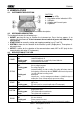
PQA820 4. NOMENCLATURE 4.1. INSTRUMENT DESCRIPTION CAPTION: 1. Indication LEDs 2. Description of the indication LEDs 3. USB port 4. Voltage and Current inputs 5. Keyboard Fig. 1: Instrument description 4.2. KEYBOARD DESCRIPTION The keyboard includes the following keys: ON/OFF: pressing this key to switches the instrument on. Press the key approx. 2s to switches the instrument off.
PQA820 5. INITIAL SETTINGS CAUTION The instrument may be configured only through the relevant management software, except for the selection of the electrical system, which may also be performed through the SYSTEM key in the instrument's keyboard 5.1. SETTING THE ELECTRICAL SYSTEM This parameter allows selecting the type of electrical system to be analyzed. It is possible to select the electrical system through the SYSTEM button in the instrument's keyboard.
PQA820 SYMBOL V1PE, V2PE, V3PE V12, V23, V31 Freq.
PQA820 SYMBOL V1, V2, V3 V12, V23, V31 Freq.
PQA820 5.2. SETTING TYPE OF CLAMP The instrument is capable of managing two types of clamp meter: STD: standard clamp with iron core Flex: flexible clamp It is also possible to differentiate the type of clamp used for phase and neutral current with independent setting of used full scales. The type of clamp selected must always be consistent with the type of clamp actually used. For further information on the settings of this parameter, please refer to the on-line guide of the management software 5.3.
PQA820 5.7. SETTING A PROGRAMMED START AND STOP Through these parameters it is possible to set the start/stop modes of a recording. In detail: START:MAN STOP:MAN START:AUTO STOP:AUTO Recording of all selected quantities will be started at the beginning of the first minute after the START/STOP key has been pressed by the operator (see § 7). Recording of all selected quantities will be manually stopped by the operator by pressing the START/STOP key (see § 7.3).
PQA820 6. MEASURING PROCEDURES 6.1. CONNECTION IN A SINGLE-PHASE SYSTEM CAUTION The maximum rated voltage between inputs is 415V AC, CAT IV 300V to earth. Do not connect the instrument to voltages exceeding the limits given in this manual The rated supply voltage of the instrument (red-yellow terminals) must be within the range: 100 415V, 50/60Hz Fig.
PQA820 6.2. CONNECTION IN A THREE-PHASE 3-WIRE SYSTEM CAUTION The maximum rated voltage between inputs is 415V AC, CAT IV 300V to earth. Do not connect the instrument to voltages exceeding the limits given in this manual The rated supply voltage of the instrument (red-yellow terminals) must be within the range: 100 415V, 50/60Hz Fig.
PQA820 6.3. CONNECTION IN A THREE-PHASE 4-WIRE SYSTEM CAUTION The maximum rated voltage between inputs is 415V AC, CAT IV 300V to earth. Do not connect the instrument to voltages exceeding the limits given in this manual The rated supply voltage of the instrument (red-yellow terminals) must be within the range: 100 415V, 50/60Hz Fig.
PQA820 7. RECORDING OF ELECTRICAL PARAMETERS 7.1. STARTING RECORDING Recording can be started MANUALLY or AUTOMATICALLY. Once the setting phase has been completed and after quitting the menu mode, the instrument will start recording by following logic illustrated hereunder: MANUAL: AUTO: Recording will start at the beginning of the minute after the START/STOP button has been pressed.
PQA820 8. MEMORY MANAGEMENTS The instrument has approximately 8MB for storing the values of the measured quantities. Through the management software it is possible to receive information about the residual recording duration compatible with the residual memory space and the settings made on the instrument itself. The instrument is also capable of saving up to 65530 voltage anomalies. For further information on this issue, please refer to the on-line guide of the management software.
PQA820 9. TRANSFERRING DATA TO THE MANAGEMENT SOFTWARE The connection between the instrument and the management may occur through: USB port by means connection with USB cable WiFi connection CAUTION It is not possible to transfer data while recording The selected port must NOT be engaged by other devices or applications (e.g. a mouse, a modem, etc.
PQA820 10. MAINTENANCE 10.1. GENERAL INFORMATION While using and storing the instrument, carefully observe the recommendations listed in this manual in order to prevent possible damage or danger during use: Do not use the instrument in environments with high humidity levels or high temperatures Do not expose to direct sunlight Always switch off the instrument after use. 10.2. CLEANING THE INSTRUMENT Use a soft and dry cloth to clean the instrument. Never use wet cloths, solvents, water, etc. 10.3.
PQA820 11. TECHNICAL SPECIFICATIONS 11.1. TECHNICAL CHARACTERISTICS Accuracy indicated as [%rdg +(num. dgt * resolution)] referred to 23°C±5°C, < 75%RH DC Voltage [Phase (+) – Neutral (-)] Range [V] 10.0 265.0 Resolution [V] 0.1 Accuracy (0.7rdg + 0.4V) Voltage values <10.0V are zeroed AC TRMS Voltage (Phase-Neutral, Phase-PE) Range [V] 10.0 265.0 Frequency [Hz] 42.5 69.0Hz Resolution [V] 0.1 Accuracy (0.5rdg + 0.2V) Maximum crest factor = 1.5, Voltage values <10.
PQA820 AC Power/Energy – (Vmeas > 200V, Pf=1) Clamp FS [A] 1< FS 10 10< FS 200 200< FS 1000 Range [W] [Wh] 0.000k 9.999k 10.00k 99.99k 0.00k 99.99k 100.0k 999.9k 0.0k 999.9k 1000k 9999k Resolution [W] [Wh] 0.001k 0.01k 0.01k 0.1k 0.1k 1k Accuracy (0.7rdg + 3W/Wh) (0.7rdg+30W/Wh) (0.7rdg+30W/Wh) (0.7rdg+300W/Wh) (0.7rdg+0.3kW/kWh) (0.7rdg+3kW/kWh) Vmeas = Voltage in which the power is measured Power factor and Cos Range 0.20 0.50 0.50 0.80 0.80 1.
PQA820 12. APPENDIX – THEORETICAL OUTLINE 12.1. VOLTAGE ANOMALIES The instrument catalogs as voltage anomalies (sags, swells) all those RMS values, calculated every 10ms (@ 50Hz), which are out of the thresholds set upon configuration by 1% to 30% of a set reference value with a 1% step. To prevent recording events attributable to electric noise only, a hysteresis threshold of 1% is also present. These limits remain unchanged throughout the whole recording period.
PQA820 12.2.
PQA820 12.2.1. Limit values for harmonics EN50160 guideline prescribes the limits for the Harmonic voltages the Supplier may put in network.
PQA820 All this generates odd harmonics of the 50/60Hz line frequency. For this reason, nowadays the current in the transformers of the distribution boxes contains not only a 50Hz (or 60Hz) component, but also a 150Hz (or 180Hz) component, a 250Hz (or 300Hz) component and other significant harmonic components up to 750Hz (or 900Hz) and above The vector sum of the currents in a fully balanced system that feeds non-linear loads may still be quite low.
PQA820 12.3.
PQA820 NOTES Please note that, strictly speaking, the expression of phase reactive power in a nonsinusoidal condition would be incorrect.
PQA820 SYMBOL P+ Pfc+ Pfi+ Qc+ Qi+ PPfcPfiQcQiVALUE P Q Pf 0 -1 MEANING Value of active power + Capacitive power factor + Inductive power factor + Value of capacitive reactive power + Value of inductive reactive power + Value of active power Capacitive power factor Inductive power factor Value of capacitive reactive power Value of inductive reactive power - NOTES Positive quantities (user user) Negative quantities (generator user) MEANING The relative (positive or negative) active power is defined in th
PQA820 12.4. INFORMATION ON THE MEASURING METHOD The instrument is capable of measuring: voltages, currents, active powers, inductive and capacitive reactive powers, apparent powers, inductive and capacitive power factors and analogical or pulse parameters. All of these parameters are analyzed in a completely digital way: for each phase (voltage and current) 128 samples per period are taken, then repeating this operation for 18 consecutive periods. 12.4.1.
PQA820 13. SERVICE 13.1. WARRANTY CONDITIONS This instrument is warranted against any material or manufacturing defect, in compliance with the general sales conditions. During the warranty period, defective parts may be replaced. However, the manufacturer reserves the right to repair or replace the product. Should the instrument be returned to the After-sales Service or to a Dealer, transport will be at the Customers charge. However, shipment will be agreed in advance.
YAMUM0060HT0 Via della Boaria 40 48018 – Faenza (RA) – Italie Tél : +39 0546-621002 (4 lignes r.a.) Fax : +39 0546-621144 E-mail : ht@htitalia.it http://www.ht-instruments.