ENGLISH User manual Copyright HT ITALIA 2012 Version EN 2.
MPP300 Table of contents: 1. PRECAUTIONS AND SAFETY MEASURES ............................................................... 2 1.1. 1.2. 1.3. 1.4. 2. GENERAL DESCRIPTION ........................................................................................... 4 2.1. 2.2. 3. Introduction........................................................................................................................ 4 Instrument functions ...........................................................................
MPP300 1. PRECAUTIONS AND SAFETY MEASURES The instrument has been designed in compliance with directive IEC/EN61010-1 relevant to electronic measuring instruments.
MPP300 1.2. DURING USE Please carefully read the following recommendations and instructions: CAUTION Failure to comply with the notes and/or instructions may damage the instrument and/or its components or be a source of danger for the operator The red flashing “POWER” LED indicates that the internal rechargeable batteries are almost flat. In this case, connect the external power supply as described in § 7.2 The IDC1, IDC2, IDC3 input connectors are type 4-pole type.
MPP300 2. GENERAL DESCRIPTION 2.1. INTRODUCTION Dear Customer, thank you for choosing one of the instruments in our range. If used according to the instructions given in this manual, the instrument you have just purchased will guarantee accurate and reliable measures.
MPP300 3. PREPARATION FOR USE 3.1. INITIAL CHECKS Before shipping, the instrument has been checked from an electric as well as mechanical point of view. All possible precautions have been taken so that the instrument is delivered undamaged. However, we recommend checking it to detect any damage possibly suffered during transport. In case anomalies are found, immediately contact the dealer. We also recommend checking that the packaging contains all components indicated in § 8.5.
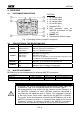
MPP300 4. OVERVIEW 4.1. INSTRUMENT DESCRIPTION CAPTION: 1. DC voltage inputs 2. DC current inputs 3. AC voltage inputs 4. AC current inputs 5. Indication LEDs 6. USB connector (only for MASTER instruments of Type 2, see § 4.3) 7. ON/OFF key 8. Connector for external supply Fig. 1: Description of the instrument’s front panel 4.2.
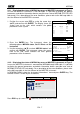
MPP300 4.3.1. Displaying the status of MPP300 by means of MASTER instruments of Type 1 In case the MASTER instrument is near MPP300, it is possible to display the general parameters and obtain information about a possible error state of MPP300 (STATUS LED red steady). For a description of the error conditions, please refer to the Message table in the User Manual of the MASTER instrument 1. Position the cursor onto EFF by using the arrow keys 15/05/10 15:34:26 (,) and confirm with ENTER.
MPP300 5. SETTINGS ON MASTER INSTRUMENTS Instructions are given according to the Type of instruments, classified according to Table 2. Further in this manual, a brief description is provided of the settings of the MASTER instrument for use together with MPP300. For an exhaustive description of the controls and functions of the MASTER instrument, please refer to the User Manual of the instrument itself. 5.1.
MPP300 6. OPERATING INSTRUCTIONS Further in this manual, a brief description is provided of the use of MPP300 together with the MASTER instrument. For an exhaustive description of the controls and functions of the MASTER instrument, please refer to the User Manual of the instrument itself. For the sake of simplicity, further in this manual, the word “string” will be used, although often the term “photovoltaic field” would be more correct.
MPP300 Fig. 3: Connection of MPP300 for testing a three-phase PV system CAUTION When SOLAR I-V is set in order to use MPP300 as a remote unit, ALL connections relevant to electrical quantities (voltages and currents) must be carried out on unit MPP300. SOLAR I-V must have no voltage nor current connected to its inputs The maximum voltage for the inputs of MPP300 is 1000VDC between inputs VDC1, VDC2, VDC3 and 600VAC between inputs VAC1, VAC2, VAC3.
MPP300 5. Bring SOLAR I-V, SOLAR-02 and unit MPP300 nearer (maximum distance of 1m between them). All instruments must be switched on (see the User Manuals of SOLAR-2 and MPP300 for further details) 6. On SOLAR I-V, press the MENU key, select the function EFF and press ENTER; wait for the three units to start communicating with each other.
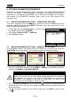
MPP300 17. The display of SOLAR I-V will show the values of the 15/05/10 15:34:26 general electrical parameters of the system being P R p - - Irr - - measured P n o m 3 . 500 In particular, in this screen: Tc - - Pdc = General dc power (sum of the string powers) Te - - dc 3.125 Pac = ac power (if single-phase) or sum of the ac powers (if P Pac 2.960 three-phase) ndc - - nac W/m2 kW °C °C kW kW 0.
MPP300 21. Upon reaching the instant “00” after pressing the GO/STOP 15/05/10 15:35:00 key, the test is started and the three units are P R p - - Irr - - synchronized with each other. In these conditions: Pnom 3.500 The display of SOLAR I-V shows the message “rec. T c - - Te - - running” Pdc 3.125 The display of SOLAR-02 shows the message P a c 2.960 ndc - - “Recording…” nac 0.95 On MPP300, the STATUS LED flashes green Select W/m2 kW °C °C kW kW Rec. running MPP 22.
MPP300 32. To stop testing, press the GO/STOP key on instrument 15/05/10 15:35:00 SOLAR I-V and confirm with ENTER that you want to stop PRp 0.82 Irr 971 recording Pnom 3.500 33. The display of SOLAR I-V will show the message “DATA T c 45.1 DOWNLOAD” to indicate that the data will be transferred to T e 30.5 Pdc 3.125 the main unit during its various phases Pac 2.960 ndc 0.86 34. After the automatic data transfer phase, the instrument: nac 0.
MPP300 6.2. PV SYSTEM TESTING FOR INSTRUMENTS OF TYPE 1 (SOLAR 300N) 6.2.1. Testing of PV systems with single/multi-MPPT inverter - single/three-phase AC output The instrument SOLAR300N, used together with remote units SOLAR-02 and MPP300 (optional), allows carrying out long recordings on PV systems characterized by 1 or more PV fields (with the same direction and inclination), each connected to an MPPT of the inverter (see § 9.1) and single-phase or three-phase output.
MPP300 CAUTION When SOLAR300N is set in order to use MPP300 as a remote unit, ALL connections relevant to electrical quantities (voltages and currents) must be carried out on unit MPP300. SOLAR300N must have no voltage nor current connected to its inputs. The maximum voltage for the inputs of MPP300 is 1000VDC between inputs VDC1, VDC2, VDC3 and 600VAC between inputs VAC1, VAC2, VAC3. Do not measure voltages exceeding the limits given in this manual.
MPP300 9. Connect the output connector of the DC clamp to the IDC1 input of unit MPP300. CAUTION BEFORE CONNECTING THE DC CLAMPS TO THE CONDUCTORS Switch on the clamp, check the LED indicating the status of the clamp’s internal batteries (if present), select the correct range, press the ZERO key on the DC clamp and check on the display of SOLAR300N the actual zeroing of the corresponding Idc value (values up to 0.02A are acceptable). 10.
MPP300 18. On SOLAR300N, press key F3 to access the second screen which contains the values of the output DC parameters of the strings according to the number of DC inputs set (see SOLAR300N user’s manual). In particular, in this screen: Vdcx = dc voltage of string x. Idcx = dc current of string x. Pdx = dc power of string x. We recommend checking that the values of the electrical parameters (Vdc, Idc, Pdc) are consistent with the system being measured.
MPP300 22. At any time while recording it will be possible to analyze its current status by selecting the button Saved data management in the GENERAL MENU. The following information will be shown: a. starting date and time of recording b. the value set for the integration period c. the number of periods elapsed from the beginning of the recording d. the remaining memory capacity for recording Press the ESC key to exit the screen 23.
MPP300 32. To stop recording, press the GO/STOP key on the instrument SOLAR300N and confirm with ENTER that you want to stop recording. 33. The display of SOLAR300N will show various messages indicating the different phases of data transfer to the main unit. The transferred data will be saved automatically. 34.
MPP300 7. MAINTENANCE 7.1. GENERAL INFORMATION The instrument you purchased is a precision instrument. While using and storing the instrument, carefully observe the recommendations listed in this manual in order to prevent possible damage or danger during use. Do not use the instrument in environments with high humidity levels or high temperatures. Do not expose to direct sunlight. Always switch off the instrument after use. 7.2.
MPP300 8. TECHNICAL SPECIFICATIONS 8.1. TECHNICAL SPECIFICATIONS FOR TEST ON PV SYSTEMS Uncertainty is indicated as [%reading + (no. of digits) * resolution] at 23°C ± 5°C, <80%HR DC voltage Range [V] 10.0 999.9 Resolution [V] 0.1 Uncertainty (0.5rdg + 2dgt) Phase-Neutral AC TRMS voltage Range [V] Frequency 10.0 300.0 42.5 69.0Hz Resolution [V] 0.1 Uncertainty (0.5rdg + 2ddgt) Resolution [V] 0.1 Uncertainty (0.
MPP300 8.2. REFERENCE STANDARDS Instrument safety: Safety of measuring accessories: Technical documentation: Insulation: Mechanical protection: Pollution level: Measurement category: IEC/EN61010-1 IEC/EN61010-031 IEC/EN61187 double insulation IP 40 2 CAT III 1000V DC, Max 1000V between DC inputs CAT IV 300V AC to earth, max 600V between AC inputs 8.3. GENERAL CHARACTERISTICS Memory Memory capacity: 2 MBytes Integration Period: 5,10,30,60,120,300,600,900,1800,3600s Battery duration (with SOLAR-02): approx.
MPP300 9. APPENDIX – THEORETICAL OUTLINE 9.1. TESTING PHOTOVOLTAIC SYSTEMS According to the requirements of the laws in force, the result of the test depends on settings about Temperature effects compensation and PRp calculations (see MASTER instrument settings): Corr.Typ e Tmod Tcel value Tcel = PV Module Temp. measured Tcel = PV module Temp. calculated PRp Tamb Gp or NOCT Tcel Tamb 20 Tenv 800 nDC Guidelin e PRp calculation Tcel = PV Module Temp.
MPP300 9.2. NOTES ON MPPT (MAXIMUM POWER POINT TRACKER) Solar irradiation on a surface such as the surface of a photovoltaic system has extremely variable characteristics, since it depends on the position of the sun with respect to the surface and on atmospheric conditions (typically, on the presence of clouds). A photovoltaic module presents, for different solar irradiation values, and for different temperature values, a range of characteristic curves of the type shown in the following figure.
MPP300 10. SERVICE 10.1. WARRANTY CONDITIONS This instrument is warranted against any material or manufacturing defect, in compliance with the general sales conditions. During the warranty period, defective parts may be replaced. However, the manufacturer reserves the right to repair or replace the product Should the instrument be returned to the After-sales Service or to a Dealer, transport will be at the Customer’s charge. However, shipment will be agreed in advance.
ESPAÑOL Manual de Instrucciones Copyright HT ITALIA 2012 Versión ES 2.
MPP300 Indice: 1. PRECAUCIONES Y MEDIDAS DE SEGURIDAD ....................................................... 2 1.1. 1.2. 1.3. 1.4. 2. DESCRIPCIÓN GENERAL ........................................................................................... 4 2.1. 2.2. 3. Introducción ....................................................................................................................... 4 Funcionalidad del instrumento .................................................................................
MPP300 1. PRECAUCIONES Y MEDIDAS DE SEGURIDAD El instrumento ha sido proyectado conforme a la directiva IEC/EN61010-1 en relación a los instrumentos de medida electronicos. Antes y durante la realización de las medidas atenerse a las siguientes indicaciones y leer con particular atención todas las notas precedidas con el símbolo ATENCIÓN Cuando el instrumento fuera utilizado en modo diverso del especificado en este manual de instrucciones, las protecciones previstas podrían verse comprometidas.
MPP300 1.2. DURANTE EL USO Le rogamos que lea atentamente las recomendaciones y las instrucciones siguientes: ATENCIÓN La falta de observación de las advertencias y/o instrucciones puede dañar el instrumento y/o sus componentes o ser fuente de peligro para el usuario El LED “POWER“ rojo intermitente indica que las baterías internas recargables están casi descargadas. Entonces conecte el alimentador externo como se describe en el § 7.
MPP300 2. DESCRIPCIÓN GENERAL 2.1. INTRODUCCIÓN Estimado Cliente, le agradecemos por haber escogido un instrumento de nuestro programa de venta. El instrumento adquirido por usted, siga lo descrito en el presente manual, le garantizará medidas exactas y fiables. El instrumento está realizado en modo de garantizarle la máxima seguridad gracias a un desarrollo de nueva concepción que asegura el doble aislamiento y la categoría de sobretensión CAT III 1000VCC y CAT IV 300VCA(respecto a Tierra).
MPP300 3. PREPARACIÓN PARA EL USO 3.1. CONTROLES INICIALES El instrumento, antes de ser enviado, ha sido controlado desde el punto de vista eléctrico y mecánico. Han sido tomadas todas las precauciones posibles para que el instrumento pueda ser entregado sin daños. Pero se aconseja controlarlo para determinar eventuales daños sufridos durante el transporte. Si se encontraran anomalías contactar inmediatamente con el distribuidor.
MPP300 4. NOMENCLATURA 4.1. DESCRIPCIÓN DEL INSTRUMENTO LEYENDA: 1. Entradas Tensiones CC 2. Entradas Corrientes CC 3. Entradas Tensiones CA 4. Entradas Corrientes CA 5. LEDs indicadores 6. Conector USB (sólo para instrumentos MASTER Tipo 2, ver § 4.3) 7. Tecla ON/OFF 8. Conector para Alim. externo Fig. 1: Descripción panel frontal del instrumento 4.2.
MPP300 4.3.1. Visualización estado MPP300 a través instrumentos MASTER de Tipo 1 Cuando el instrumento MASTER se encuentre en proximidad del MPP300, se pueden visualizar los parámetros generales y tener informaciones acerca de un posible estado de error del MPP300 (LED STATUS rojo fijo). Para la descripción de las condiciones de error vease en el manual de instrucciones del instrumento MASTER la Tabla de los mensajes. 1.
MPP300 5. PROGRAMACIÓN INSTRUMENTOS MASTER Las instrucciones se dan por Tipología de instrumentos clasificados según la Tabla 2. Seguidamente se muestra una descripción mínima de las configuraciones del instrumento MASTER para el uso en combinación al MPP300. Para la descripción completa de los comandos y funcionalidad del instrumento MASTER véase el manual de instrucciones del instrumento. 5.1. INSTRUCCIONES PARA MASTER TIPO 1- CONFIGURACIÓN U.
MPP300 6. INSTRUCCIONES OPERATIVAS Se hace referencia a una descripción mínima acerca de la utilización del MPP300 en combinación al Instrumento MASTER. Para la descripción completa de los comandos y funcionalidades del Instrumento MASTER ver el manual de instrucciones del instrumento. Para simplificar, a partir de este parágrafo se adoptará el término “[string]” aunque a menudo el término “campo fotovoltaico” sería más oportuno.
MPP300 Fig. 3: Conexión del MPP300 para verificación de una Instalación FV Trifásica ATENCIÓN Cuando el SOLAR I-V está configurado para utilizar el MPP300 como Unidad Remota TODAS las conexiones relativas a magnitudes eléctricas (Tensiones y corrientes) se realizan sobre la Unidad MPP300. El SOLAR I-V no debe tener ninguna tensión o corriente conectada a las propias entradas.
MPP300 5. Acérquelos entre ellos (max 1m aprox.) el SOLAR I-V, el SOLAR-02 y la unidad MPP300. Todos los instrumentos tienen que estar encendidos (ver los manuales de uso del SOLAR-2 y MPP300 para más detalles). 6. Sobre el SOLAR I-V pulse la tecla MENU, seleccione la función CLD y pulse ENTER y espere que las tres unidades inicien la comunicación entre ellas.
MPP300 20. Ponga nuevamente en servicio el sistema eléctrico en examen. 21. En el visualizador del SOLAR I-V se visualizarán los 15/05/10 15:34:26 valores de los parámetros elécticos totales del sistema P R p - - examinado. Irr - - P n o m 3 . 500 En particular en esta pantalla: Tc - - Pdc = Potencia CC total (suma de las potencias del [string]) T e - - dc 3.125 Pac = Potencia CA (monofásica) o suma de las potencias P Pac 2.960 CA (trifásica) ndc - - nac W/m2 kW °C °C kW kW 0.
MPP300 25. Al alcanzar el instante ”00” sucesivo a la presión de la 15/05/10 15:35:00 tecla GO/STOP inicia la verificación y las tres unidades P R p - - Irr - - se sincronizan entre sí. En tales condiciones: nom 3.500 En el visualizador del SOLAR I-V aparece el mensaje “reg. P Tc - - en curso”. Te - - dc 3.125 En el visualizador del SOLAR-02 aparece el mensaje P Pac 2.960 ndc - - “Recording…” nac 0.95 En el MPP300 parpadea en verde el LED STATUS W/m2 kW °C °C kW kW reg. en curso Selección MPP 26.
MPP300 36. Para detener la verificación pulse la tecla GO/STOP en el 15/05/10 15:35:00 Instrumento SOLAR I-V y confirme con ENTER la solicitud Irr 971 W/m2 de detención del registro Pnom 3.500 kW 45.1 °C 37. Sobre el visualizador del SOLAR I-V se visualizará el T c Te 30.5 °C mensaje “DESCARGA DATOS” que indica la transferencia P d c 3.125 kW Pac 2.960 kW de los datos hacia la unidad principal en sus varias fases. ndc 0.86 38. Después de la fase automática de transferencia de datos, en n a c 0.
MPP300 6.2. CHEQUEO INSTAL. FV PARA INSTRUMENTOS DE TIPO 2 (SOLAR300N) 6.2.1. Testeo Instal. FV con Inverter Mono/Multi MPPT - Salida CA mono/trifásico El instrumento SOLAR300N vinculado a las unidades remotas SOLAR-02 y MPP300 (opcional) permite ejecutar verificaciones sobre instalaciones FV caracterizadas por 1 o más campos FV (con la misma orientación e inclinación) cada uno conectado con un MPPT del inverter (vea §9.2) y salida Monofase o Trifase.
MPP300 ATENCIÓN Cuando el SOLAR300N está configurado para utilizar el MPP300 como unidad remota TODAS las conexiones relativas a magnitudes eléctricas (Tensiones y Corrientes) se realizan sobre la unidad MPP300. El SOLAR300N no debe tener ninguna tensión o corriente conectada a entradas propias. La máxima tensión para las entradas del MPP300 es de 1000VCC entre las entradas VDC1,VDC2, VDC3 y 600VCA entre las entradas VAC1, VAC2, VAC3. No mida tensiones que excedan los límites expresados en este manual.
MPP300 10. Conecte el conector de salida de la pinza CC en la entrada IDC1 de la unidad MPP300. ATENCIÓN ANTES DE CONECTAR LAS PINZAS CC SOBRE LOS CONDUCTORES Encienda la pinza, controle el LED que indica el estado de las baterías internas de la pinza (si estuvieran presentes), seleccione el alcance correcto, pulse la tecla ZERO sobre la pinza CC y verifique sobre el visualizador del SOLAR300N la efectiva puesta a cero del valor Idc correspondiente (valores hasta 0.02A son no obstante aceptables). 11.
MPP300 22. Sobre el SOLAR300N pulse la tecla F3 para acceder a la segunda pantalla que reporta los valores de los parámetros CC en salida en las stringhe de acuerdo con el número de entradas CC configurado (vea el manual de instrucciones del SOLAR300N). En particular en esta pantalla: Vdcx=Tensión CC de la stringa x. Idcx=Corriente CC de la stringa x. Pdx = Potencia CC de la stringa x.
MPP300 26. En cualquier momento del registro será posible analizar el estado actual de la misma seleccionando en el MENU GENERAL el botón Gestión Datos memorizados. Se mostrarán: a. Fecha y hora del inicio del registro b. El valor configurado del periodo de integración c. El número de Períodos transcurridos desde el inicio del registro d. La capacidad de memoria restante del registro. Pulse la tecla ESC para salir de la pantalla 27.
MPP300 36. Para detener la verificación pulse la tecla F1 en el instrumento SOLAR300N y confirme con ENTER la petición de detener el registro 37. En el visualizador del SOLAR300N se mostrarán varios mensajes indicativos de las distintas fases de transferencia de los datos hacia la unidad principal. 38.
MPP300 7. MANTENIMIENTO 7.1. GENERALIDADES El instrumento que Usted ha adquirido es un instrumento de precisión. Durante el uso y el almacenamiento respete las recomendaciones enumeradas en este manual para evitar posibles daños o peligros durante el uso. No utilice el instrumento en entornos caracterizados por elevadas tasas de humedad o temperatura. No lo exponga directamente a la luz del sol. Apague siempre el instrumento después del uso 7.2.
MPP300 8. ESPECIFICACIONES TÉCNICAS 8.1. CARACTERÍSTICAS TÉCNICAS VERIFICACIÓN INSTALACIONES FV incertidumbre indicada como [%lectura + (num. cifras)* resolución] a 23°C ± 5°C, <80%HR Tensión CC Campo [V] 10.0 999.9 Resolución [V] 0.1 Incertidumbre (0.5lectura + 2cifras) Tensión CA TRMS Fase - Neutro Campo [V] Frecuencia 10.0 346.0 42.5 69.0Hz Resolución [V] 0.1 Incertidumbre (0.5lectura + 2cifras) Resolución [V] 0.1 Incertidumbre (0.
MPP300 8.2. NORMAS DE REFERENCIA Seguridad instrumento: Seguridad accessorios de medida: Documentación técnica: Aislamiento: Grado de protección: Grado de contaminación: Categoria de medida: IEC/EN61010-1 IEC/EN61010-031 IEC/EN61187 doble aislamiento IP 40 2 CAT III 1000V CC, Max 1000V entre las entradas CC CAT IV 300VCA respecto tierra, Max 600V entre entradas CA 8.3.
MPP300 9. APENDICE – CONCEPTOS TEÓRICOS 9.1. VERIFICACIÓN DE LAS INSTALACIONES FV De acuerdo con los requisitos de la legislación vigente, el resultado de la prueba depende de la configuración de compensación de temperatura y efectos de los cálculos de PRp: Tipo Corr. Tmod Temperatura utilizada (Tcel) Cálculo del PRp Tcel Tmodulos_Medida PRp Tcel = T modulos calc.
MPP300 9.2. CONCEPTOS SOMBRE MPPT (MAXIMUM POWER POINT TRACKER) La irradiación solar sobre una superficie como la de una instalación fotovoltáica tiene características altamente variables, siendo dependiente de la posición del sol respecto a la superficie y de las características de la atmósfera (típicamente por la presencia de nubes).
MPP300 10. ASISTENCIA 10.1. CONDICIONES DE GARANTÍA Este instrumento está garantizado contra cada defecto de materiales y fabricaciones, conforme con las condiciones generales de venta. Durante el período de garantía, las partes defectuosas pueden ser sustituidas, pero el fabricante se reserva el derecho de repararlo o bien sustituir el producto. Siempre que el instrumento deba ser reenviado al servicio post - venta o a un distribuidor, el transporte será a cargo del cliente.
DEUTSCH Bedienungsanleitung Copyright HT ITALIA 2012 Ausführung DE 2.
MPP300 Inhalt 1. VORKEHRUNGEN UND SICHERHEITSMAßNAHMEN .............................................. 2 1.1. 1.2. 1.3. 1.4. 2. ALLGEMEINE BESCHREIBUNG ................................................................................. 4 2.1. 2.2. 3. Einführung ......................................................................................................................... 4 Instrument funktionen .......................................................................................................
MPP300 1. VORKEHRUNGEN UND SICHERHEITSMAßNAHMEN Dieses Instrument wurde in Übereinstimmung mit den Sicherheits-Standards IEC/EN 61010-1 für elektronische Mess-Instrumente entwickelt. Zu Ihrer eigenen Sicherheit und der des Messgerätes befolgen Sie bitte die in dieser Anleitung beschriebenen Abläufe, und lesen Sie mit äußerster Aufmerksamkeit die mit diesem vorgestellten Symbol gekennzeichneten Anmerkungen.
MPP300 1.2. WÄHREND DER VERWENDUNG WARNUNG Fehler in der Übereinstimmung mit den Warnungen und/oder den Anweisungen können das Instrument und/oder seine Bestandteile beschädigen oder eine Gefahrenquelle für den Anwender sein. Die rote aufblitzende " LEISTUNG "-LEUCHTDIODE zeigt, dass die inneren wiederaufladbaren Batterien fast leer sind. In einem solchen Fall schließen Sie ein externes Ladegerät an - wie beschrieben in § 7.2. Die IDC1, IDC2, IDC3 Eingangsbuchsen sind 4-polig.
MPP300 2. ALLGEMEINE BESCHREIBUNG 2.1. EINFÜHRUNG Lieber Kunde, wir danken Ihnen für die Wahl eines Instrumentes aus unserem Sortiment. Wenn es entsprechend den Anweisungen in diesem Handbuch eingesetzt wird, wird das Instrument, das Sie gerade gekauft haben, genaue und zuverlässige Messungen garantieren.
MPP300 3. VORBEREITUNG FÜR DIE ANWENDUNG 3.1. ERSTE ÜBERPRÜFUNGEN Vor dem Versenden ist das Instrument hinsichtlich der Elektrik sowie der Mechanik überprüft worden. Alle möglichen Vorkehrungen wurden getroffen, damit das Instrument unbeschädigt geliefert wird. Aber wir empfehlen, es auf mögliche Schäden zu überprüfen, die möglicherweise während Transportes entstanden sein könnten. Falls Anomalien gefunden werden, verständigen Sie sofort Ihren Fachhändler.
MPP300 4. NOMENKLATUR 4.1. INSTRUMENTEN-BESCHREIBUNG LEGENDE: 1. DC Spannungs-Eingänge 2. DC Strom-Eingänge 3. AC Spannungs-Eingänge 4. AC Strom-Eingänge 5. Anzeige LEDs 6. USB Anschluss (nur für MASTER Instrumente vom Typ 2, siehe § 4.3) 7. AN/AUS - Schalter 8. Anschluss für externe Stromversorgung Abb. 1: Beschreibung des Instrumenten Bedienfeldes 4.2.
MPP300 4.3.1. Status Anzeige vom MPP300 mittels MASTER Instrument Typ 1 Sofern sich das MASTER Instrument in unmittelbarer Nähe dem MPP300 befindet, ist es möglich, die allgemeinen Parameter anzuzeigen und Informationen über einen möglichen Fehler-Status vom MPP300 (Anzeige leuchtet dauernd rot) zu erhalten. Für eine Beschreibung der Fehlerbedingungen, beziehen Sie sich bitte auf die Mitteilungs-Tabelle in der Bedienanleitung vom MASTER Instrument. 15/05/10 15:34:26 1.
MPP300 5. BETRIEBSANLEITUNGEN FÜR DAS MASTER INSTRUMENT Anweisungen werden entsprechend dem Instrumenten-Typus gegeben, eingestuft gemäß Tabelle 2. Weiterhin ist in diesem Handbuch eine Kurzbeschreibung mit den Einstellungen für den Gebrauch des MASTER Instrumentes zusammen mit dem MPP300 vorhanden. Für eine detaillierte Beschreibung der Steuerungsfunktionen des MASTER Instrumentes, beziehen Sie sich bitte auf die Bedienanleitung vom Instrument selbst 5.1.
MPP300 6. BEDIENUNGSANLEITUNG In diesem Handbuch ist eine Kurzbeschreibung für den Gebrauch des MPP300 zusammen mit dem MASTER Instrument verfügbar. Für eine detaillierte Beschreibung der Steuerungsfunktionen des MASTER Instrumentes, beziehen Sie sich bitte auf die Bedienanleitung vom Instrument selbst. Aus Gründen der Einfachheit wird außerdem in diesem Handbuch das Wort "String" benutzt, obwohl oftmals der Begriff “PV Anlage“ korrekter wäre.
MPP300 Abb. 3: Anschluss des MPP300 zum Testen eines 3-Phasen-PV System WARNUNG Wenn das SOLAR I-V so eingestellt ist um das MPP300 zu nutzen, müssen ALLE Anschlüsse bezogen auf elektrische Quantitäten (Spannungen und Ströme) am MPP300 angeschlossen sein. Am SOLAR I-V dürfen weder Spannung noch Strom an seinen Eingängen anliegen. Die maximale Spannung für die Eingänge vom MPP300 ist 1000V DC zwischen den Eingängen VDC1, VDC2, VDC3 und 600V AC zwischen den Eingängen VAC1, VAC2, VAC3.
MPP300 5. Auf dem SOLAR I-V, drücken Sie die MENU Taste, wählen Sie die Funktion EFF und drücken ENTER; warten Sie bis die drei Geräte anfangen miteinander zu kommunizieren. Dieser Zustand wird durch die Gegenwart der folgenden Meldungen hervorgehoben: dauernd (nicht blinkend) auf dem Display des SOLAR I-V Symbol Symbol dauernd (nicht blinkend) auf dem Display des SOLAR-02 MASTER und REMOTE LEDs grün blinkend auf dem Gerät MPP300 6.
MPP300 17. Das Display von SOLAR I-V wird die Werte der 15/05/10 15:34:26 allgemeinen elektrischen Parameter des zu messenden P R p - - Irr - - W/m2 elektrischen Systems zeigen Pnom 3.500 kW Insbesondere, in diesem Bildschirm: Tc - - °C Pdc = Allgemeine DC Generatorleistung (Summe der T e - - °C Pdc 3.125 kW Stringleistungen) Pac 2.960 kW Pac = AC Leistung (wenn 1-phasig) oder Summe der AC- n d c - - nac 0.
MPP300 21. Beim Erreichen des Erscheinen von " 00 " nach dem 15/05/10 15:35:00 Drücken der GO/STOP Taste, wird die Messung P R p - - - - W/m2 begonnen und die drei Geräte sind mit einander I r r P n o m 3 . 5 0 0 kW synchronisiert: Tc - - °C Das Display vom SOLAR I-V zeigt die Meldung “rec. T e - - °C Pdc 3.125 kW running” Pac 2.960 kW - - Das Display vom SOLAR-02 zeigt die Meldung n d c nac 0.95 “Aufzeichnung…” Auf dem MPP300 blinkt die STATUS LED grün Rec. running Select MPP 15/05/10 15:35:00 22.
MPP300 31. Drücken Sie Taste am SOLAR-02 zum Aktivieren der RF Verbindung nochmals. Folgerichtig wird das Haupt-Gerät die Meldung zeigen “Radio Verbindung aktiviert” 32. Zum Stoppen der Messung, drücken Sie die GO/STOP 15/05/10 15:35:00 Taste am SOLAR I-V und bestätigen mit ENTER dass Sie PRp 0,82 Irr 971 die Aufzeichnung beenden wollen. Pnom 3.500 33. Das Display vom SOLAR I-V wird die Meldung “DATA T c 45.1 DOWNLOAD” anzeigen, die Daten werden dem Haupt- T e 30.5 Pdc 3.125 Gerät automatisch übergeben.
MPP300 6.2. PV SYSTEMTEST FÜR INSTRUMENTS VOM TYP 2 (SOLAR 300N) 6.2.1. PV Systeme mit multi-MPPT Inverter - Ein-/Drei-Phasen AC Ausgang Das Instrument SOLAR 300N, eingesetzt zusammen mit dem SOLAR-02 und MPP300, erlaubt die Überprüfung von PV Systemen mit Multistring-Wechselrichter sowie 1-Phasen 2 oder 3-Phasen-Ausgang. (Voraussetzung: FW Version > = 1.27 beim SOLAR300N und FW Version > = 5.00 bei SOLAR02).
MPP300 WARNUNG Wenn das SOLAR 300N so eingestellt ist um das MPP300 zu nutzen, müssen ALLE Anschlüsse bezogen auf elektrische Quantitäten (Spannungen und Ströme) am MPP300 angeschlossen sein. Am SOLAR 300N dürfen weder Spannung noch Strom an seinen Eingängen anliegen. Die maximale Spannung für die Eingänge vom MPP300 ist 1000V DC zwischen den Eingängen VDC1, VDC2, VDC3 und 600V AC zwischen den Eingängen VAC1, VAC2, VAC3.
MPP300 11. Verbinden Sie die VDC1(+) und VDC1(-) Eingänge vom Gerät MPP300 mit Hilfe geeigneter Adapter und Messleitungen mit den beiden Enden der Stringleitung, unter Berücksichtigung der Polarität und der Farben angegeben in Abb.4 oder Abb. 5 12. Wiederholen Sie die Operation, die in den zwei Schritten oben beschrieben wird, für die VDC2 und VDC3 Eingänge sofern beim Wechselrichters weitere DC Leistungseinheiten (MPPT, Multistring oder Mix Modus) vorhanden sind. 13.
MPP300 22.
MPP300 25. Bringen Sie das SOLAR300N, das SOLAR-02 und das MPP300 nah zusammen (maximale Entfernung 1m untereinander, das SOLAR300N muss über das USB Kabel mit dem MPP300 verbunden sein. 26. Drücken Sie zum Start der Messaufzeichnung die Taste F1 (Start mit Standardeinstellung) oder GO/ STOP (Start mit individuellen Einstellungen) auf dem SOLAR300N. a. Das SOLAR300N wird in den STAND-BY Modus wechseln und zur vollen Minute (bzw.
MPP300 37. Um die Aufzeichnung zu beenden, verbinden Sie zunächst das MPP-300 über das USB Kabel mit dem SOLAR300N. Drücken die anschließend die F1 Taste 38. Das Display vom SOLAR300N wird die Meldung “DATA DOWNLOAD” anzeigen. Das MPP300 wird nun automatisch die aufgezeichneten Daten (inkl. der Daten vom SOLAR-02) an das SOLAR300N übertragen (Synchronisation) und abschließend den während der Aufzeichnung ermittelten besten Wirkungsgrad anzeigen.
MPP300 7. WARTUNG 7.1. ALLGEMEINE INFORMATIONEN Das Instrument, das Sie kauften, ist ein Präzisionsinstrument. Während der Benutzung und Lagerung des Instrumentes beachten Sie die Empfehlungen, die in diesem Handbuch aufgezählt werden, zur Vermeidung möglicher Schäden oder Gefahr während der Verwendung. Benutzen Sie das Instrument nicht in Umgebungen mit hoher Luftfeuchtigkeitspegels oder hohen Temperaturen. Exponieren Sie es nicht direktem Sonnenlicht. NACH DEM GEBRAUCH immer das Instrument ausschalten 7.
MPP300 8. TECHNISCHE SPEZIFIKATIONEN 8.1. TECHNISCHE SPEZIFIKATIONEN ZUM TESTEN VON PV SYSTEMEN Ungenauigkeit gezeigt als [%Abl. + (Anz. Digits) * Auflösung] bei 23°C ± 5°C, <80%HR DC Spannung Bereich [V] 10.0 999.9 Auflösung [V] 0.1 Genauigkeit (0.5Ablesung + 2 Digits) Phase-Neutralleiter AC TRMS Spannung Bereich [V] Frequenz Auflösung [V] 0.1 10.0 300.0 42.5 69.0Hz Genauigkeit (0.5Ablesung + 2 Digits) Max peak Faktor: 1,5 Phase-Phase AC TRMS Spannung Bereich [V] Frequenz 50.0 594.0 42.
MPP300 8.2. NORMEN Instrumentensicherheit. Sicherheit vom Messzubehör : Technische Dokumentation: Isolation: Schutzklasse: Verschmutzungsgrad: Messkategorie: IEC/EN61010-1 IEC/EN61010-031 IEC/EN61187 Doppelte Isolation IP 40 2 CAT III 1000V DC, Max 1000V zwischen DC Eingängen CAT IV 300V AC g. Erde, max. 600V z. den AC Eing. 8.3. ALLGEMEINE MERKMALE Speicher Speicherkapazität: 2 MBytes Integrationsperiode: 5,10,30,60,120,300,600,900,1800,3600s Speicherkapazität (mit SOLAR-02): ungefähr 1.
MPP300 9. THEORETISCHER ANHANG 9.1. ERMITTLUNG DES PRP In Abhängigkeit der jeweiligen nationalen Vorschriften kann die Messung an einer PV Anlage zu folgendem Ergebnis führen: Messwerte werden nicht angezeigt: sofern die ermittelten Messwerte zu einem nicht konsistenten Ergebnis führen ( z.B. PRp >1.15) oder sofern die Einstrahlung nie einen stabilen Wert erreicht hat bzw. den min. Grenzwert nie überschritten hat (siehe auch Anleitung vom MASTER Instrument).
MPP300 9.2. MPPT (MAXIMUM POWER POINT TRACKER) Die Einstrahlungsstärke von Oberflächen wie jene von PV Modulen ist extremen Umgebungsänderungen unterworfen, weil sie vom Einfallswinkel der Sonnenstrahlen auf die PV Moduloberfläche und den Wetterbedingungen (wie beispielsweise Wolken) abhängt. In Abhängigkeit der Einstrahlungsstärke der Außentemperatur ergeben sich bei PV Modulen charakteristische U-I Kennlinien wie sie in der folgenden Abbildung als Beispiel dargestellt sind.
MPP300 Arbeitsbedingungen zu steuern. Durch die MPP-Regelung arbeiten Ihre Solarmodule immer im optimalen Wirkungsgrad. 10. SERVICE 10.1. GARANTIE-BEDINGUNGEN Dieses Instrument erhält gemäß den allgemeinen Geschäftsbedingungen eine Garantie von 2 Jahren ab Kaufdatum bezüglich jeglicher Material- und Herstellungsfehler. In der gesamten Garantiezeit behält sich der Hersteller das Recht vor, das Produkt zu reparieren oder zu ersetzen.
FRANÇAIS Manuel d’utilisation Copyright HT ITALIA 2012 Version FR 2.
MPP300 Table des matières : 1. PRECAUTIONS ET MESURES DE SECURITE........................................................... 2 1.1. 1.2. 1.3. 1.4. 2. DESCRIPTION GENERALE ......................................................................................... 4 2.1. 2.2. 3. Introduction........................................................................................................................ 4 Fonctions de l'instrument .......................................................................
MPP300 1. PRECAUTIONS ET MESURES DE SECURITE Cet instrument a été conçu conformément à la directive IEC/EN61010-1 relative aux instruments de mesure électroniques. Avant et pendant l’exécution des mesures, veuillez respecter ces indications et lire attentivement toutes les remarques précédées du symbole . ATTENTION Au cas où l'on utiliserait l'instrument d'une façon différente par rapport à ce qui est spécifié dans ce manuel d'utilisation, les protections prévues pourraient être compromises.
MPP300 1.2. PENDANT L’UTILISATION Veuillez lire attentivement les recommandations et instructions suivantes : ATTENTION Le non-respect des avertissements et/ou instructions pourrait endommager l’instrument et/ou ses composants ou mettre en danger l’utilisateur. La DEL « POWER » rouge clignotante indique que les batteries internes rechargeables sont presque épuisées. Dans ce cas-là, connecter le chargeur externe en respectant la procédure décrite à la § 7.
MPP300 2. DESCRIPTION GENERALE 2.1. INTRODUCTION Cher Client, nous vous remercions d'avoir choisi un instrument de notre programme de vente. Si l'instrument que vous venez d'acheter est utilisé dans le respect de ce qui est décrit dans ce manuel, il garantit des mesures soignées et fiables.
MPP300 3. PREPARATION A L'UTILISATION 3.1. VERIFICATION INITIALE L’instrument a fait l’objet d’un contrôle mécanique et électrique avant d’être expédié. Toutes les précautions possibles ont été prises pour garantir une livraison de l’instrument en bon état. Toutefois, il est recommandé de le contrôler afin de détecter des dommages qui auraient pu avoir lieu pendant le transport. En cas d’anomalies, n’hésitez pas à contacter votre revendeur.
MPP300 4. NOMENCLATURE 4.1. DESCRIPTION DE L’INSTRUMENT LEGENDE : 1. Entrées tensions DC 2. Entrées courants DC 3. Entrées tensions AC 4. Entrées courants AC 5. Indicateurs DEL 6. Connecteur USB (seulement pour instruments MASTER de type 2, voir la § 4.3) 7. Allumage/extinction 8. Conn. pour charg. externe Fig. 1 : Description du panneau frontal de l’instrument 4.2.
MPP300 4.3.1. Affichage de l'état MPP300 à l'aide d'instruments MASTER de type 1 Si l'instrument MASTER se trouve à proximité de l’MPP300, on peut afficher les paramètres généraux et avoir des informations sur l'état d'erreur éventuel de l’MPP300 (STATUS de la DEL rouge fixe). Pour la description des conditions d'erreur, voir le Tableau des messages dans le manuel d'utilisation de l'instrument MASTER. 1. Placer le curseur sur EFF à l'aide des touches fléchées 15/05/10 15:34:26 (, ) et confirmer par ENTER.
MPP300 5. PROGRAMMATION POUR L'INSTRUMENT MASTER Les instructions sont fournies par type d'instrument dans le respect du classement du Tableau 2. On fournira par la suite une brève description des réglages de l'instrument MASTER pour l’utilisation avec MPP300. Pour la description complète des commandes et des fonctions de l'instrument MASTER, voir le manuel d'utilisation de l'instrument même. 5.1.
MPP300 6. MODE D'UTILISATION On fournira par la suite une brève description de l'utilisation de MPP300 associé à l'instrument MASTER. Pour la description complète des commandes et des fonctions de l'instrument MASTER, voir le manuel d'utilisation de l'instrument même. Par simplicité, dans la suite de cette section on adoptera le terme « chaîne » même s'il serait souvent plus opportun d'utiliser le terme « champ photovoltaïque ».
MPP300 Fig. 3 : Connexion du MPP300 pour essai d'une installation PV Triphasée ATTENTION Lorsque le SOLAR I-V est réglé de sorte à utiliser le MPP300 en tant qu'unité à distance, TOUTES les connexions relatives aux grandeurs électriques (tensions et courants) doivent être exécutées sur l'unité MPP300. Le SOLAR I-V ne doit avoir ni de tension ni de courant connectés à ses entrées.
MPP300 5. Approcher entre eux (1m environ maximum) le SOLAR I-V, le SOLAR-02 et l’unité MPP300. Tous les instruments doivent être allumés (voir les manuels d'utilisation de SOLAR-2 et MPP300 pour plus de détails). 6. Dans le SOLAR I-V, appuyer sur la touche MENU, sélectionner la fonction EFF et appuyer sur ENTER ; attendre jusqu'à ce que les trois unités ne commencent à communiquer entre elles.
MPP300 17. L'afficheur du SOLAR I-V montrera les valeurs des 15/05/10 15:34:26 paramètres électriques totaux du système sous test. Irr - - W/m2 Notamment, dans cette page-écran : Pnom 3.500 kW T c ° C Pdc = Puissance DC totale (somme des puissances de Te - - °C chaîne) Pdc 3.125 kW ac 2.960 kW Pac = Puissance AC (si monophasée) ou somme des P ndc - - puissances AC (si triphasée) nac 0.95 On recommande de contrôler que les valeurs des G o d é p a r t e n r e g t .
MPP300 21. Une fois l'instant « 00 » atteint après avoir appuyé sur la 15/05/10 15:35:00 touche GO/STOP, l'essai commence et les trois unités I r r - - W/m2 sont synchronisées entre elles. Dans de telles P n o m 3.500 kW T c ° C conditions : Te - - °C L'écran du SOLAR I-V affiche le message « Enregt. En P d c 3.125 kW Pac 2.960 kW cours... ». ndc - - 0.95 L'écran du SOLAR-02 affiche le message « Recording... ». n a c Sur le MPP300 le LED STATUS (état de la DEL) clignote en Enregt. En cours... vert.
MPP300 32. Pour arrêter l'essai, appuyer sur la touche GO/STOP sur 15/05/10 15:35:00 l'instrument SOLAR I-V et confirmer par ENTER à la Irr 971 demande d'arrêt de l'enregistrement. Pnom 3.500 45.1 33. Sur l'afficheur du SOLAR I-V on affichera le message TT ce 30.5 « TELECHARGER », ce qui indique le transfert des données P d c 3.125 Pac 2.960 à l'unité principale dans ses différentes phases ndc 0.86 34.
MPP300 6.2. ESSAI D'INSTALLATIONS PV POUR INSTRUMENTS DE TYPE 2 (SOLAR 300N) 6.2.1. Essai installations avec inverseur Mono/Multi MPPT - Sortie AC mono/triphasée L'instrument SOLAR300N associé aux unités à distance SOLAR-02 et MPP300 (en option) permet d'effectuer des essais sur des installations PV caractérisées par 1 ou plusieurs champs PV (ayant la même orientation et inclinaison) chacun étant connecté à un MPPT de l'inverseur (voir la § 9.2) et sortie Monophasée ou Triphasée.
MPP300 ATTENTION Lorsque le SOLAR300N est réglé de sorte à utiliser le MPP300 en tant qu'unité à distance, TOUTES les connexions relatives aux grandeurs électriques (tensions et courants) doivent être exécutées sur l'unité MPP300. Le SOLAR300N ne doit avoir ni de tension ni de courant connectés à ses entrées. La tension maximale pour les entrées du MPP300 est de 1000VDC entre les entrées VDC1, VDC2, VDC3 et de 600VAC entre les entrées VAC1, VAC2, VAC3.
MPP300 ATTENTION AVANT DE CONNECTER LES PINCES DC SUR LES CONDUCTEURS Allumer la pince, contrôler la DEL qui indique le niveau des piles internes de la pince (si présentes), sélectionner la portée correcte, appuyer sur la touche ZERO sur la pince DC et vérifier sur l'écran du SOLAR300N la mise à zéro effective de la valeur Idc correspondante (des valeurs jusqu'à 0.02A sont quand même acceptées). 9.
MPP300 17. Dans le SOLAR300N, appuyer sur la touche F3 pour accéder à la deuxième page-écran qui liste les valeurs des paramètres DC de sortie aux chaînes conformément au nombre d'entrées DC réglé (voir le manuel d'utilisation du SOLAR300N).
MPP300 21. A tout moment de l'enregistrement il sera possible d'analyser son état actuel en sélectionnant dans le MENU GENERAL la touche Résultats d’enregistrement. On affichera : a. la date et l'heure de départ de l’enregistrement ; b. la valeur réglée dans la période d'intégration ; c. le nombre de périodes qui se sont écoulées du début de l'enregistrement ; d. la capacité de mémoire résiduelle d'enregistrement. Appuyer sur la touche ESC pour quitter cette pageécran. 22.
MPP300 31. Pour arrêter l'essai, appuyer sur la touche F1 sur l'instrument SOLAR300N et confirmer par ENTER à la demande d'arrêt de l'enregistrement. 32. L'écran du SOLAR300N affichera les messages qui indiquent les différentes phases du transfert des données vers l'unité principale 33. Après la phase automatique de transfert des données, sur l'instrument on affichera automatiquement les valeurs de performance maximale.
MPP300 7. ENTRETIEN 7.1. ASPECTS GENERAUX L’instrument que vous avez acheté est un instrument de précision. Pour son utilisation et son stockage, veuillez suivre attentivement les recommandations et les instructions indiquées dans ce manuel afin d’éviter tout dommage ou danger pendant l’utilisation. Ne pas utiliser l’instrument dans des endroits ayant un taux d’humidité et/ou de température élevé. Ne pas exposer l’instrument en plein soleil. Toujours éteindre l’instrument après utilisation. 7.2.
MPP300 8. SPECIFICATIONS TECHNIQUES 8.1. CARACTERISTIQUES TECHNIQUES ESSAI D'INSTALLATIONS PV Incertitude est indiquée [%lecture + (num. digits) * résolution] à 23°C ± 5°C, <80%HR Tension DC Echelle [V] 10.0 999.9 Résolution [V] 0.1 (0.5lect+2dgts) Tension AC TRMS Phase-Neutre Echelle [V] Fréquence 10.0 300.0 42.5 69.0Hz Résolution [V] 0.1 Incertitude (0.5lect+2dgts) Résolution [V] 0.1 Incertitude (0.
MPP300 8.2. NORMES DE REFERENCE Sécurité instrument : Sécurité des accessoires de mesure : Documentation technique : Isolement : Degré de protection : Degré de pollution : Catégorie de mesure : IEC/EN61010-1 IEC/EN61010-031 IEC/EN61187 double isolement IP 40 2 CAT III 1000V DC, max 1000V entre les entrées DC CAT IV 300V AC à la terre, max 600V entre entrées AC 8.3.
MPP300 9. APPENDICE - NOTIONS THEORIQUES 9.1. ESSAI DES INSTALLATIONS PV Conformément à ce qui est prévu par la réglementation en vigueur, le résultat du test dépend des réglages de température sur les effets de compensation et de calculs de PRp Type Corr. Valeur des Tcel Tmod Tcel = PV Module Temp. mesuré Relation mathématique pour le calcul de PRp PRp Tcel = PV module Temp. calculé Tamb Gp ou Tenv Tcel Tamb NOCT 20 800 nDC Tcel = PV Module Temp.
MPP300 9.2. NOTIONS SUR MPPT (MAXIMUM POWER POINT TRACKER) Le rayonnement solaire sur une surface comme celle d'une installation photovoltaïque possède des caractéristiques très variables, comme il dépend de la position du soleil par rapport à cette surface et des caractéristiques de l'atmosphère (normalement de la présence de nuages).
MPP300 10. ASSISTANCE 10.1. CONDITIONS DE GARANTIE Cet instrument est garanti contre tout défaut de matériel ou de fabrication, conformément aux conditions générales de vente. Pendant la période de garantie, toutes les pièces défectueuses peuvent être remplacées, mais le fabricant se réserve le droit de réparer ou de remplacer le produit. Si l’instrument doit être renvoyé au service après-vente ou à un revendeur, le transport est à la charge du Client.
YAMUM0046HT0 Via della Boaria, 40 48018 – Faenza (RA)- Italy Tel: +39-0546-621002 (4 linee r.a.) Fax: +39-0546-621144 Email: ht@htitalia.it http://www.ht-instruments.