User manual MACROTESTG3 – COMBIG3 Copyright HT ITALIA 2014 Release EN 1.
MACROTESTG3 - COMBIG3 Table of contents: 1. PRECAUTIONS AND SAFETY MEASURES ............................................................... 3 1.1. 1.2. 1.3. 1.4. 2. GENERAL DESCRIPTION ........................................................................................... 5 2.1. 2.2. 3. Initial checks ...................................................................................................................... 7 Instrument power supply ........................................................
MACROTESTG3 - COMBIG3 6.9. ΔV%: Voltage drop of main lines ..................................................................................... 71 6.9.1. 7. 7.1. 7.2. Saving measurements..................................................................................................... 77 Recalling measurements and deleting the memory ........................................................ 78 7.2.1. 8. Anomalous situations ..........................................................................
MACROTESTG3 - COMBIG3 1. PRECAUTIONS AND SAFETY MEASURES The instrument has been designed in compliance with directives IEC/EN61557 and IEC/EN61010-1 relevant to electronic measuring instruments. Before and after carrying out the measurements, carefully observe the following instructions: Do not carry out any voltage or current measurement in humid environments. Do not carry out any measurements in case gas, explosive materials or flammables are present, or in dusty environments.
MACROTESTG3 - COMBIG3 1.2. DURING USE Please carefully read the following recommendations and instructions: CAUTION Failure to comply with the caution notes and/or instructions may damage the instrument and/or its components or be a source of danger for the operator. Before changing function, disconnect the test leads from the circuit under test. When the instrument is connected to the circuit under test, never touch any terminal, even if unused.
MACROTESTG3 - COMBIG3 2. GENERAL DESCRIPTION 2.1. FOREWORD If used according to the instructions given in this manual, the instrument you have just purchased will guarantee accurate and reliable measures. This manual refers to MACROTESTG3 and COMBIG3 models. The characteristics of the models are listed in the following Table 1: In the whole manual, the word “instrument” generically indicates MACROTESTG3 model, unless otherwise indicated.
MACROTESTG3 - COMBIG3 2.2. INSTRUMENT FUNCTIONS The instrument is equipped with a TFT color LCD display, with capacitive "touch-screen" that can be handled simply with the touch of a finger by the user and is structured with an icon-based menu allowing the direct selection of measurement functions for quick and intuitive use.
MACROTESTG3 - COMBIG3 3. PREPARATION FOR USE 3.1. INITIAL CHECKS Before shipping, the instrument has been checked from an electric as well as mechanical point of view. All possible precautions have been taken so that the instrument is delivered undamaged. However, we recommend checking it to detect any damage possibly suffered during transport. In case anomalies are found, immediately contact the Dealer. We also recommend checking that the packaging contains all the components indicated in § 10.5.
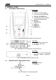
MACROTESTG3 - COMBIG3 4. NOMENCLATURE 4.1. INSTRUMENT DESCRIPTION CAPTION: 1. Inputs 2. LCD Touch screen display 3. Function keys F1, F2, F3, F4 4. ,, , / ENTER keys 5. Compartment of the connector for optical cable/USB port 6. ESC key 7. GO/STOP key 8. HELP key 9. SAVE key 10. ON/OFF key Fig. 1: Description of the front part of the instrument CAPTION: 1. Connector for remote probe 2. B1, B2, B3, B4 inputs 3. In1 input Fig. 2: Description of the upper part of the instrument CAPTION: 1.
MACROTESTG3 - COMBIG3 4.3.
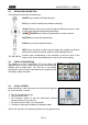
MACROTESTG3 - COMBIG3 5. GENERAL MENU Pressing the ENTER key in any condition of the instrument allows to go back to the general menu in which internal parameters may be set, the saved measures can be displayed and the desired measuring function may be selected. Fig. 5: General menu of the instrument Touch the icon to move to the following page of the general menu and the icon go back to the previous page. Inside the screens, touch the icon or the icon 5.1. to exit without confirming.
MACROTESTG3 - COMBIG3 5.1.2. Automatic Power OFF for display and key sound Touch the display. icon. The screen to the side appears on the Move the slide bar reference of section " " down/up to turn off/on the Automatic Power OFF of the instrument after a period of inactivity of 5 minutes. " down/up to Move the slide bar reference of section " disable/enable the sound key when pressed. Confirm the choices made and go back to the previous screen. 5.1.3.
MACROTESTG3 - COMBIG3 6. OPERATING INSTRUCTIONS 6.1. LOW: CONTINUITY OF PROTECTIVE CONDUCTORS This function is performed in compliance with standards IEC/EN61557-4 and allows measuring the resistance of protective and equipotential conductors. CAUTION The instrument can be used for measurements on installations with overvoltage category CAT III 240V to earth and CAT III 415V between inputs.
MACROTESTG3 - COMBIG3 1. icon. The screen to the side appears on Touch the the display. The instrument automatically carries out the test for the presence of voltage between the inputs (shown on the display) and blocks the test in case of voltage higher than 10V Touch the “AUTO” icon to set the measuring mode. The following screen appears on the display: 2. Move the slide bar reference in the positions "AUTO" (Automatic mode) or " " (Timer mode). Confirm the choice by going back to the previous screen.
MACROTESTG3 - COMBIG3 5. Perform, if necessary, the compensation of the measuring leads resistance by connecting the cables or the remote lead as shown in Fig. 7. Fig. 7: Compensation of single cables and remote lead resistance 6. Touch the icon to activate the measurement. After a few seconds, the instrument provides the screen to the side if the operation is successful (Rcables 2); the indication of the value is shown in the "Rcal" field and the icon is shown on the display.
MACROTESTG3 - COMBIG3 10. At the end of the test, if the value of the measured resistance is higher than the set limit, the screen to the side is shown on the display. The value is shown in red and the symbol indicates the negative result of the measurement. The "> 99.9" message indicates the instrument overload status. Press the SAVE button or touch the the measurement (see § 7.1). icon to save 6.1.1. Anomalous situations 1.
MACROTESTG3 - COMBIG3 6.2. M: MEASUREMENT OF INSULATION RESISTANCE This function is performed in compliance with standards IEC/EN61557-2 and allows measuring the insulation resistance between the active conductors and between each active conductor and the earth. CAUTION The instrument can be used for measurements on installations with overvoltage category CAT III 240V to earth and CAT III 415V between inputs.
MACROTESTG3 - COMBIG3 1. 2. Touch the icon. The screen to the side appears on the display. The instrument automatically carries out the test for the presence of voltage between the inputs (shown on the display) and blocks the test in case of voltage higher than 10V Touch the “AUTO” icon to set the measuring mode. The following screen appears on the display: Move the slide bar reference in the positions "AUTO" (Automatic mode) or " " (Timer mode). Confirm the choice by going back to the previous screen.
MACROTESTG3 - COMBIG3 CAUTION Disconnect any cable not strictly involved in measurement and especially check that no cable is connected to In1 input. Before connecting the test leads, make sure that there is no voltage at the ends of the conductors to be tested. 6. Connect the alligator clips and/or test leads and/or remote lead to the ends of the conductors to be tested as in Fig. 8 and Fig. 9. 7. Press the GO/STOP key on the instrument or the START key on the remote lead.
MACROTESTG3 - COMBIG3 6.2.1. Anomalous situations 1. If the instrument measures a resistance higher than the set limit value but for which it is not able to generate the rated voltage, the screen to the side is displayed. The symbol is shown on the display and the values of the real test voltage are indicated in red. 2. If the instrument detects a voltage value higher than 10V at its terminals, it does not carry out the test, gives out a long sound and the screen reported here to the side is displayed.
MACROTESTG3 - COMBIG3 6.3. RCD: TEST ON DIFFERENTIAL SWITCHES This function is performed in compliance with standard IEC/EN61557-6 and allows measuring the tripping time and current of molded case differential switches of type A ( ), AC ( ) and B ( ), being General (G), Selective (S) and Delayed ( ).
MACROTESTG3 - COMBIG3 Fig. 12: Connection for a 400V + N + PE three-phase system by means of single cables and remote lead Fig. 13: Connection for a 400V + N (no PE) three-phase system by means of single cables and remote lead [no for RCD type B] Fig. 14: Connection for a 400V + PE (no N) system with single cables and remote lead Fig.
MACROTESTG3 - COMBIG3 1. Touch the icon. The screen to the side appears on the display. Touch the icon to the left to set the RCD operating mode. The following screen appears on the display: 2. Move the slide bar reference by selecting the desired operating mode between the options: G (General), S (Selective), (Delayed). Confirm the choice by going back to the initial measurement screen. Note the presence of the chosen selection. When selecting a Delayed RCD, the instrument displays the following screen.
MACROTESTG3 - COMBIG3 5. 6. 7. Touch the icon to zero the value in “A” field and use the virtual keyboard to set the value of rated current of earth leakage relay RCD. The maximum rated current is 10.0A. Confirm the choice by going back to the previous screen. Move the second slide bar reference by selecting the waveform of the differential switch between the options: (type AC), (type A), (type B).
MACROTESTG3 - COMBIG3 6.3.1. AUTO mode 9. Press the GO/STOP key on the instrument or the START key on the remote lead. The instrument will start the measurement. The screen to the side is shown on the display when the hourglass icon indicates the performance of the test.
MACROTESTG3 - COMBIG3 6.3.2. x½, x1, x2, x5 modes 9. Press the GO/STOP key on the instrument or the START key on the remote lead. The instrument will start the measurement. The screen to the side (concerning multiplier x1) is shown on the display when the hourglass icon indicates the performance of the test.
MACROTESTG3 - COMBIG3 6.3.4. Mode The standard defines, for molded case type STD, the tripping times for RCDs at nominal current. The mode is used to detect the minimum tripping current (which could also be lower than the nominal voltage). 9. Press the GO/STOP key on the instrument or the START key on the remote lead. The instrument will start the measurement. The screen to the side is shown on the display when the hourglass icon indicates the performance of the test.
MACROTESTG3 - COMBIG3 6.3.5. Test on earth leakage relay RCD The instrument allows performing tests on earth leakage relay RCD with currents up to 10A (with optional accessory RCDX10) 8. Connect the instrument and the optional accessory RCDX10 to the installation (see Fig. 15). Pay attention to the connection of cables “1” and “2” of the RCDX10 accessory and to the direction of the current indicated by the arrow printed on the accessory.
MACROTESTG3 - COMBIG3 6.3.6. Anomalous situations 1. If the voltage between inputs B1 and B4 and inputs B1 and B3 is higher than 265V, the instrument provides the warning screen shown to the side and blocks the execution of the tests. 2. If the voltage between inputs B1 and B4 and inputs B1 and B3 is lower than 100V, the instrument provides the warning screen shown to the side and blocks the execution of the tests. 3.
MACROTESTG3 - COMBIG3 6. If the instrument detects that the phase and neutral leads are inverted, it does not carry out the test and a screen similar to the one reported to the side is displayed. Rotate the shuko plug or check the connection of measuring cables. 7. If the instrument detects that the phase and PE leads are inverted, it does not carry out the test and a screen similar to the one reported to the side is displayed. Check the connection of measuring cables. 8.
MACROTESTG3 - COMBIG3 11 If the instrument detects a voltage Vn-pe > 50V (or the analogue Vn-pe >25V) it provides the warning screen shown to the side and blocks the test for safety reasons. Check the PE conductor and earth plant efficiency 12 If the instrument detects in the input terminals a too high external impedance such that it can not provides the nominal current, it provides the warning screen shown to the side and blocks the test.
MACROTESTG3 - COMBIG3 6.4. LOOP: LINE IMPEDANCE/LOOP AND OVERALL EARTH RESISTANCE This function is performed in compliance with standard IEC/EN61557-3 and allows measuring the line impedance, the fault loop impedance and the prospective short-circuit current.
MACROTESTG3 - COMBIG3 Fig. 18: P-N/P-PE measurement for 400V+N+PE three-phase systems by means of single cables and remote lead Fig. 19: P-P measurement for 400V+N+PE three-phase systems Fig. 20: P-PE/P-N measurement for 400V + PE (no N) systems by means of single cables and remote lead Fig.
MACROTESTG3 - COMBIG3 6.4.1. Test types The protection of electrical lines is the essential part of a project so as to guarantee the correct functionality and avoid damages to persons or property. To this purpose, the safety guidelines impose on electrical designers also to design the electrical installation in order to reach: 1.
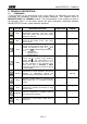
MACROTESTG3 - COMBIG3 The following table summarizes the possible measures executable depending on the type of system (TT, TN and IT), of selected modes and the relationships that define limit values L-L Mode TT Condition x OK outcome TN Condition x OK outcome IT Condition x OK outcome STD No outcome No outcome No outcome kA Isc L-L max < BC I2t (Isc L-L 3F)2 * t < (K * Isc L-L max < BC S)2 (IscL-Lmin 2F) Tmax Tmax < Tlim L-N L-PE (Isc L-L3F)2 * t < (K * Isc L-L max < BC S)2 (Isc
MACROTESTG3 - COMBIG3 This mode performs the impedance measurement and the calculation of prospective short circuit current without applying any evaluation. Therefore, at the end of the test, no outcome is given by the instrument. 1. Select the options “TN, TT or “IT”, “25 or 50V”, “50Hz or 60Hz” and the reference voltage in the general settings of the instrument (see § 5.1.3). Touch the the display. icon. The screen to the side appears on Touch the lower icon.
MACROTESTG3 - COMBIG3 6. The value of the assumed short-circuit current (Isc) is shown in the upper part of the display, while the Line/Loop ZPE impedance is shown at the bottom of the display. Press the SAVE button or touch the the measurement (see § 7.1).
MACROTESTG3 - COMBIG3 6.4.3. Mode kA – Verify of breaking capacity of protection device 1. Select the options “TN, TT or “IT”, “25 or 50V”, “50Hz or 60Hz” and the reference voltage in the general settings of the instrument (see § 5.1.3). Touch the the display. icon. The screen to the side appears on Touch the lower icon. The following screen appears on the display: 2.
MACROTESTG3 - COMBIG3 5. Press the GO/STOP key or the START key on the remote lead. During this whole stage, do not disconnect the measuring leads of the instrument from the system under test. In case of positive outcome, the screen to the side is shown by the instrument. Press the SAVE button or touch the the measurement (see § 7.1). icon to save 6. In case of test failure (measured Isc Max current > set threshold), the screen to the side is displayed by the instrument.
MACROTESTG3 - COMBIG3 6.4.4.
MACROTESTG3 - COMBIG3 4. Touch the icon to zero the value in the In field and use the virtual keyboard to set the value of the RCD rated current within the values allowed by the instrument. The following selections are available on the instrument MCB current (B curve) selectable among: 6,10,13,15,16,20,25,32,40,50,63A MCB current (C, K curves) selectable among: 0.5,1,1.6,2,4,6,10,13,15,16,20,25,32,40,50,63A MCB current (D curve) selectable among: 0.5,1,1.
MACROTESTG3 - COMBIG3 6. If possible, disconnect all loads connected downstream of the measured point, as the impedance of these users could distort the test results. Connect the shuko plug, the alligator clips or the remote lead to the electrical mains according to Fig. 16, Fig. 17, Fig. 18 and Fig. 20. Note the presence of the correct voltage values between L-L and L-PE corresponding to the selections carried out in the initial phase (see § 5.1.3) as shown in the screen to the side 7.
MACROTESTG3 - COMBIG3 6.4.5. Mode - Verify of protection coordination 1. Select the options “TN, TT or “IT”, “25 or 50V”, “50Hz or 60Hz” and the reference voltage in the general settings of the instrument (see § 5.1.3). Touch the the display. icon. The screen to the side appears on Touch the lower icon. The following screen appears on the display: 2.
MACROTESTG3 - COMBIG3 5. Move the slide bar reference by selecting the protection tripping time between the options: 0.1s, 0.2s, 0.4s, 5s. Confirm the choice by going back to the initial measurement screen. 6. If possible, disconnect all loads connected downstream of the measured point, as the impedance of these users could distort the test results. Connect the shuko plug, the alligator clips or the remote lead to the electrical mains according to Fig. 16, Fig. 17, Fig. 18 and Fig.
MACROTESTG3 - COMBIG3 6.4.6. Verify of protection against indirect contacts (TN system) 1. Select the options "TN", “25 or 50V”, “50Hz or 60Hz” and the reference voltage in the general settings of the instrument (see § 5.1.3). Touch the the display. icon. The screen to the side appears on Touch the lower icon. The following screen appears on the display: 2. Move the left slide bar reference by selecting the icon to execute the measurement.
MACROTESTG3 - COMBIG3 6. If possible, disconnect all loads connected downstream of the measured point, as the impedance of these users could distort the test results. Connect the alligator clips or the remote lead to the electrical mains according to Fig. 16, Fig. 17, Fig. 18 and Fig. 20 in the farthest possible point respect the protection on test. Note the presence of the correct voltage values between L-N and L-PE corresponding to the selections carried out in the initial phase (see § 5.1.
MACROTESTG3 - COMBIG3 6.4.7. Verify of protection against indirect contacts (IT systems) 1. Select the options "IT", “25 or 50V”, “50Hz or 60Hz” and the reference voltage in the general settings of the instrument (see § 5.1.3). Touch the the display. icon. The screen to the side appears on Touch the lower icon. The following screen appears on the display: 2. Move the left slide bar reference by selecting the icon to execute the measurement.
MACROTESTG3 - COMBIG3 6.4.8. Verify of protection against indirect contacts (TT systems) 1. Select the options "TT", “25 or 50V”, “50Hz or 60Hz” and the reference voltage in the general settings of the instrument (see § 5.1.3). Touch the the display. icon. The screen to the side appears on Touch the lower icon on the left. The following screen appears on the display: 2. Move the left slide bar reference by selecting the icon to execute the measurement.
MACROTESTG3 - COMBIG3 5. Press the GO/STOP key or the START key on the remote lead. During this whole stage, do not disconnect the measuring leads of the instrument from the system under test. In case of positive result (overall earth resistance lower than the ratio between limit contact voltage and RCD tripping current), the screen to the side is displayed by the instrument, which contains the contact voltage value in the secondary display. Press the SAVE button or touch the the measurement (see § 7.1).
MACROTESTG3 - COMBIG3 6.4.9. Impedance measurement by means of the accessory IMP57 Impedance measurements performed with the optional accessory IMP57 involve its connection to the Master unit (MACROTESTG3 or COMBIG3) via optical connector through the optical cable/RS-232 C2001 supplied with same accessory. The IMP57 must be directly powered by the mains on which measurements are performed. For detailed information, please refer to the user manual of the accessory IMP57.
MACROTESTG3 - COMBIG3 4. The symbol indicates the correct connection and recognition of the IMP57 by the instrument. Check the green STATUS LED lighting on the IMP57. The value of the voltage between the measurement points is shown in the upper part of the display. Press the GO/STOP key on the instrument to start the test. The following screen is shown on the display (in case of L-L measurement in STD mode) 5. The standard (STD) short-circuit current is shown in the upper part of the display.
MACROTESTG3 - COMBIG3 6.4.10. Anomalous situations 1. If the instrument detects an L-N or L-PE voltage higher than the maximum limit (265V), it does not carry out the test and displays a screen like the one to the side. Check the connection of measuring cables. 2. If the instrument detects an L-N or L-PE voltage lower than the minimum limit (100V), it does not carry out the test and displays a screen like the one to the side. Check that the system being tested is supplied. 3.
MACROTESTG3 - COMBIG3 6. If the instrument detects that the phase and neutral leads are inverted, it does not carry out the test and a screen similar to the one reported to the side is displayed. Rotate the shuko plug or check the connection of measuring cables. 7. If the instrument detects that the phase and PE leads are inverted, it does not carry out the test and a screen similar to the one reported to the side is displayed. Check the connection of measuring cables. 8.
MACROTESTG3 - COMBIG3 6.5. SEQ: PHASE SEQUENCE AND PHASE CONCORDANCE TEST This function is performed in compliance with standards IEC/EN61557-7 and allows testing the phase sequence and concordance by direct contact with live parts (not on cables with insulating sheath). The following operating modes are available: 1T 2T one lead measurement two leads measurement. Fig. 22: Phase sequence check of 1T phases with terminal and remote lead Fig.
MACROTESTG3 - COMBIG3 3. Insert the blue and black connectors of the single cables in the corresponding input terminals of the instrument B4, B1 (2T measurement). Insert in the free end of the cables the corresponding alligator clips or tips. It is also possible to use the remote lead by inserting its multipolar connector into the input lead B1. Connect the alligator clips, the tips or the remote lead to phase L1 and N according to Fig. 22 and Fig. 23. 4.
MACROTESTG3 - COMBIG3 8. At the end of the test, if the detected phase sequence is correct, the instrument displays a screen like the one shown to the side (result "1-2-3"). Press the SAVE button or touch the the measurement (see § 7.1). icon to save 9. At the end of the test, if the two detected voltages are in phase (phase concordance between two distinct three-phase systems), the instrument displays a screen like the one to the side (result "1-1-").
MACROTESTG3 - COMBIG3 6.5.1. Anomalous situations 1. If between the test start and the acquisition of the first voltage or between the acquisition of the first and second voltage, a time longer than around 10s has elapsed, the instrument displays a screen like the one to the side. 2. If the instrument detects an input voltage higher than the maximum limit, it will display a screen like the one to the side. 3.
MACROTESTG3 - COMBIG3 6.6. LEAKAGE: LEAKAGE CURRENT MEASUREMENT Using an external clamp, this function allows measuring the leakage current (by means of the optional accessory HT96U). Fig. 24: Indirect measurement of leakage current in three-phase systems Fig. 25: Direct measurement of leakage current in three-phase systems 1. Touch the the display. icon. The screen to the side appears on Touch the icon in the lower left corner to set the full scale of the clamp used.
MACROTESTG3 - COMBIG3 CAUTION Possible additional earth connections could influence the measured value. In case of real difficulty in removing them, we recommend performing the measurement in an indirect way. 5. The value of the measured leakage current appears in real time on the display as shown in the screen to the side. Press the SAVE button or touch the the measurement (see § 7.1).
MACROTESTG3 - COMBIG3 6.7. EARTH: MEASUREMENT OF EARTH RESISTANCE The MACROTESTG3, MOD1, MOD2 models (or COMBIG3 with EARTH function enabled) allows performing the measurement of earth resistance of an installation in the following ways: Measurement of earth resistance with 3-wire or 2-wire voltammetric method Measurement of ground resistivity () with Wenner 4-wire method Measurement of resistance of individual rods without disconnecting them by means of the optional clamp T2100 6.7.1.
MACROTESTG3 - COMBIG3 Fig. 27: Two-wire earth resistance measurement using an auxiliary rod Fig. 28: Two-wire earth resistance measurement from the panel board Fig.
MACROTESTG3 - COMBIG3 1. Select the options “TN, TT or “IT”, “25 or 50V”, “50Hz or 60Hz” and the reference voltage in the general settings icon. The of the instrument (see § 5.1.3). Touch the screen to the side (TT and IT systems) is shown on the display. The instrument automatically carries out the test in presence of voltage between the inputs (shown on the display) and blocks the test in case of voltage higher than 10V Touch the first icon in the lower left corner to set the measuring mode.
MACROTESTG3 - COMBIG3 5. Touch the icon to zero the value in the "A" field and use the virtual keyboard to set the value of fault current (declared by the Energy distribution board) between 1A and 9999A. Confirm the choice by going back to the initial measurement screen. Touch the icon in the lower right corner to set the tripping time of the RCD. The following screen appears on the display: 6.
MACROTESTG3 - COMBIG3 11Drive the auxiliary rods into the ground keeping to the distance instructions provided by the standards (see § 12.12.1). 12Connect the alligator clips to the auxiliary rods and to the installation under test according to Fig. 26, Fig. 27, Fig. 28 or Fig. 29. 13 Press the GO/STOP key. During this whole stage, do not disconnect the measuring leads of the instrument from the system under test. The symbol is shown on the display for the entire duration of the test.
MACROTESTG3 - COMBIG3 16 For earth resistance measurement in TN systems, in case of positive result (see § 12.11), the screen to the side is displayed by the instrument. It contains the value of contact voltage in the secondary display, the value of contact resistance of the voltage probe (Rs) and the value of contact resistance of the current probe (Rh). icon to save Press the SAVE button or touch the the measurement (see § 7.1).
MACROTESTG3 - COMBIG3 6.7.2. Earth measurement with optional clamp T2100 This measurement allows evaluating the partial resistances of the single earth rods of complex ring networks without disconnecting them and performs the calculation of the corresponden parallel resistance. Please refer to the user manual of clamp T2100 for specific details. The following measurement methods are available: Measurement of rod resistance with direct connection of clamp T2100 to the instrument.
MACROTESTG3 - COMBIG3 1. Select the options “TN, TT or “IT”, “25 or 50V”, “50Hz or 60Hz” and the reference voltage in the general settings icon, of the instrument (see § 5.1.3). Touch the touch the first icon in the lower left corner and set the measurement mode (see § 6.7.1 point 2). The following screen appears on the display. The icon indicates that the clamp T2100 is not connected to the instrument or is not in "RS232" mode.
MACROTESTG3 - COMBIG3 5. After the insertion of the value of the first rod it will be not possible to transfer the eventually measrements saved inside the T2100 by means the key. Perform the same procedure for each rod of the network in question. At the end of the measurements, press the GO/STOP key on the instrument. The following screen appears on the display 6. The RA field shows the value of the resistances in parallel performed on each rod of the earth network considered.
MACROTESTG3 - COMBIG3 6.7.3. Anomalous situations in 3-wire and 2-wire earth measurements 1. When starting a measurement, if the instrument detects an interfering voltage higher than 10V at the volt and ampere circuits input, it does not perform the test and displays the screen to the side. 2. When starting a measurement, the instrument checks the continuity of measuring cables.
MACROTESTG3 - COMBIG3 6.8.
MACROTESTG3 - COMBIG3 4. The measured value appears on the display in real time as shown in the screen to the side. Press the SAVE button or touch the the measurement (see § 7.1).
MACROTESTG3 - COMBIG3 6.9. ΔV%: VOLTAGE DROP OF MAIN LINES This feature allows to evaluating the percentage value of voltage drop between two points of a main line in which a protection device is installed and comparing this value to possible limit value specified by guidelines. The following modes are available: L-N L-L Measurement of Phase to Neutral line impedance. The test can be performed also with high resolution (0.1m) with optional accessory IMP57 Measurement of Phase to Phase line impedance.
MACROTESTG3 - COMBIG3 1. Select the option “50Hz or 60Hz” and the reference Phase-Neutral or Phase-Phase voltage in the general settings of the instrument (see § 5.1.3). Touch the icon and then the icon. The screen to the side appears on the display. Touch the lower left icon to set the type of measurement. The following screen appears on the display 2. Move the second slide bar reference and select the type of measurement between the options: L-L (PhasePhase measurement) or L-N (Phase-Neutral measurement).
MACROTESTG3 - COMBIG3 5. Touch the icon to zero the value in the “%” field and use the virtual keyboard to set the value of V% in the range 1% to 99%. Confirm the selection and go back to the previous screen 6. Go to step no. 9 in case the value of Z1 (Offset) has been set manually. In case of the value of Z1 (Offset) has NOT been manually set connect the instrument to the initial point of the main line being tested (typically downstream to a protection device) according to Fig. 32 or Fig.
MACROTESTG3 - COMBIG3 10 Press the GO/STOP key on the instrument to measure the Z2 impedance and complete the V% voltage drop measurement. During this whole stage, do not disconnect the measuring leads of the instrument from the system being tested In case of positive result (maximum percentage value of calculated voltage drop according to § 12.
MACROTESTG3 - COMBIG3 6.9.1. Anomalous situations 1. If the instrument detects an L-N or L-PE voltage higher than the maximum limit (265V), it does not carry out the test and displays a screen like the one to the side. Check the connection of measuring cables 2. If the instrument detects an L-N or L-PE voltage lower than the minimum limit (100V), it does not carry out the test and displays a screen like the one to the side. Check that the system being tested is supplied 3.
MACROTESTG3 - COMBIG3 6. If the instrument detects that the phase and neutral leads are inverted, it does not carry out the test and a screen similar to the one reported to the side is displayed. Rotate the shuko plug or check the connection of measuring cables 7. If the instrument detects that the phase and PE leads are inverted, it does not carry out the test and a screen similar to the one reported to the side is displayed. Check the connection of measuring cables 8.
MACROTESTG3 - COMBIG3 7. OPERATIONS WITH THE MEMORY 7.1. SAVING MEASUREMENTS The structure of the memory area (999 locations), of "tree" type with the possibility to expand/hide the nodes, allows the division up to 3 markers nested so as to finalize the precise locations of the measuring points with the insertion of test results.
MACROTESTG3 - COMBIG3 7.2. 1. RECALLING MEASUREMENTS AND DELETING THE MEMORY icon in the general menu. The screen Touch the to the side appears on the display. Each measurement is identified by the icons (test (test with negative result). with positive result) or Touch the desired measurement to select it on the display. Touch the icon to recall the measurement result. The following screen appears on the display: 2.
MACROTESTG3 - COMBIG3 7.2.1. Anomalous situations 1. In case there is no measure saved and the instrument memory is accessed, a screen similar to the one reported here to the side is displayed. 2. In case tries to define a new sub-node over the 3rd level the instrument provides the warning screen shown to the side and blocks the operation 3. In case tries to create a sub-node by using a just used name, the instrument provides the warning screen shown to the side and is necessary to define a new name 4.
MACROTESTG3 - COMBIG3 8. CONNECTING THE INSTRUMENT TO A PC The connection between a PC and the instrument can be done via a serial port (see Fig. 3) by means of an optical cable/USB C2006 or by means of an optical/wiFi adapter (optional accessory C2013). Before making the connection in USB mode, it is necessary to install on the PC the C2006 cable drivers present in the supplied CD-ROM in addition to the management software.
MACROTESTG3 - COMBIG3 9. MAINTENANCE 9.1. GENERAL INFORMATION While using and storing the instrument, carefully observe the recommendations listed in this manual in order to prevent possible damage or danger during use. Do not use the instrument in environments with high humidity levels or high temperatures. Do not expose to direct sunlight. Always switch off the instrument after use.
MACROTESTG3 - COMBIG3 10. TECHNICAL SPECIFICATIONS Accuracy is calculated as: ±[%reading + (no. of digits) * resolution] at 23°C, <80%RH. Refer to the Table 1 for the correspondence between models and availbale features 10.1. TECHNICAL CHARACTERISTICS AC TRMS voltage Range [V] 15 460 Resolution [V] 1 Accuracy (3%rdg + 2digits) Frequency Range [Hz] 47.0 63.6 Resolution [Hz] 0.1 Accuracy (0.1%reading+1digit) Continuity of protective conductor (LOW) Range [] Resolution [] 0.01 0.01 9.
MACROTESTG3 - COMBIG3 First fault current – IT systems Range [mA] 0.1 0.9 1 999 Resolution [mA] 0.
MACROTESTG3 - COMBIG3 Test on RCD without integral current breaking device (with accessory RCDX10) Differential protection type (RCD): Voltage range Phase-Earth, Phase-Neutral: Rated tripping currents (IN): Frequency: AC ( ), A ( ), B( ) – Generali (G), Selettivi (S) e Ritardati ( ) 100V 265V RCD type AC and A, 190V 265V RCD type B 0.
MACROTESTG3 - COMBIG3 Contact voltage (measured during RCD and Ra test) Range [V] Resolution [V] 0.1 0 Ut LIM Accuracy -0%, +(5.0 rdg + 3V) Contact voltage (EARTH test – TT systems) Range [V] Resolution [V] 0.1 0 99.9 Accuracy -0%, +(5.0 lettura + 3V) Contact voltage (EARTH test – TN systems) Range [V] Resolution [V] 0.1 0 99.9 1 100 999 Accuracy -0%, +(5.0 rdg + 3V) -0%, +(5.0 rdg + 3V) Earth resistance (MACROTESTG3 / COMBIG3 enabled) Range [] Resolution [] 0.01 0.01 9.99 0.1 10.
MACROTESTG3 - COMBIG3 10.2.
MACROTESTG3 - COMBIG3 11. SERVICE 11.1. WARRANTY CONDITIONS This instrument is warranted against any material or manufacturing defect, in compliance with the general sales conditions. During the warranty period, defective parts may be replaced. However, the manufacturer reserves the right to repair or replace the product. Should the instrument be returned to the After-sales Service or to a Dealer, transport will be at the Customers charge. However, shipment will be agreed in advance.
MACROTESTG3 - COMBIG3 12. THEORETICAL APPENDIXES 12.1. CONTINUITY OF PROTECTIVE CONDUCTORS Purpose of the test Check the continuity of: Protective conductors (PE), main equalizing potential conductors (EQP), secondary equalizing potential conductors (EQS) in TT and TN-S systems Neutral conductors having functions of protective conductors (PEN) in TN-C system.
MACROTESTG3 - COMBIG3 12.2. INSULATION RESISTANCE Purpose of the test Check that the insulation resistance of the installation complies with the requirements of the applicable guidelines. This test has to be performed with the circuit being tested not powered and with the possible loads it supplies disconnected.
MACROTESTG3 - COMBIG3 12.3. CHECKING CIRCUIT SEPARATION Definitions A SELV system is a zero-category system or safety extra low voltage system characterized by power supply from an independent (e.g. batteries, small generator set) or safety source (e.g. safety transformer), protective separation from other electrical systems (double or reinforced insulation or earthed metal screen) and absence of earthed points (insulated from the earth).
MACROTESTG3 - COMBIG3 EXAMPLE OF SEPARATION TEST BETWEEN ELECTRICAL CIRCUITS Insulation or safety transformer separating the circuits TEST BETWEEN ACTIVE PARTS Connect an instrument probe to one of the two conductors of the separated circuit and the other to one of the conductors of a nonseparated circuit. TEST BETWEEN ACTIVE PARTS AND EARTH Connect an instrument probe to one of the two conductors of the separated circuit and the other to the equalizing potential node.
MACROTESTG3 - COMBIG3 12.4. TEST ON DIFFERENTIAL SWITCHES (RCD) Purpose of the test Checking that the General (G) and Selective (S) and Delayed ( ) differential protection devices have been correctly installed and adjusted and that they maintain their characteristics over time.
MACROTESTG3 - COMBIG3 12.5. VERIFY OF THE BREAKING CAPACITY OF PROTECTION DEVICES Purpose of the test Checking that the breaking capacity of the protection device is higher than the maximum fault current possible in the system. Parts of the system to be checked The test must be performed at the point in which the maximum short-circuit current is possible, normally immediately downstream of the protection device to be checked.
MACROTESTG3 - COMBIG3 12.6.
MACROTESTG3 - COMBIG3 Depending on the set values of phase-phase, phase-neutral or phase-PE voltage (see § 5.1.3) and the measured value of fault loop impedance, the instrument calculates the minimum value of the assumed short-circuit current to be interrupted by the protection device. For proper coordination, this value MUST always be greater than or equal to the Ia value of the tripping current of the type of protection considered. The Ia reference value (see Fig.
MACROTESTG3 - COMBIG3 12.7. VERIFY OF PROTECTION AGAINST INDIRECT CONTACTS IN TT SYSTEMS Purpose of the test Checking that the protection device is coordinated with the value of earth resistance. We cannot assume a priori a reference limit value for earth resistance as a reference when checking the measurements result. It is necessary to check each time that the coordination prescribed by the standard is met. Parts of the system to be checked Earth installation in operating conditions.
MACROTESTG3 - COMBIG3 12.8. VERIFY OF PROTECTION AGAINST INDIRECT CONTACTS IN IT SYSTEMS In IT systems the active parts must be isolated from the ground or be connected to earth through an impedance of sufficiently high value. In the case of a single earth fault current of the first fault is weak and therefore it is not necessary to interrupt the circuit. This connection can be made to the neutral point of the system or to an artificial neutral point.
MACROTESTG3 - COMBIG3 12.9. VERIFY OF PROTECTION COORDINATION L-L, L-N AND L-PE Purpose of the test Test the coordination of protective devices (typically MCB or fuse) present in a Singlephase or Three-phase installation as a function of the limit time of fault extinction by the protection set by the user and the calculated value of the short-circuit current.
MACROTESTG3 - COMBIG3 CAUTION The instrument must be used to measure fault loop impedance values at least 10 times higher than the resolution value of the instrument in order to minimize errors. Depending on the set values of nominal voltage (see § 5.1.3) and the measured value of fault loop impedance, the instrument calculates the minimum value of the assumed shortcircuit current to be interrupted by the protection device.
MACROTESTG3 - COMBIG3 12.10. VERIFY OF THE PROTECTION AGAINST SHORT CIRCUITS – TEST I2T The I2t parameter represents the specific energy (expressed in A2s) let through by the protective device in short-circuit condition. The I2t energy must be able to be supported both by the cables and by the distribution bars.
MACROTESTG3 - COMBIG3 12.11. VERIFICATION OF VOLTAGE DROP ON MAIN LINES Measurement voltage drop as a result of current flow through a main line or a part of it can be very important if it is necessary: Verify the capability of an existing main line to supply a load Dimension a new installation Search for possible causes of troubles on devices, loads, etc..
MACROTESTG3 - COMBIG3 Check that the measured value of earth resistance is lower than the maximum limit calculated on the basis of the maximum allowable contact voltage Utp for the system. In accordance with the requirements of standard EN50522 the maximum allowable contact voltage is dependent on the time duration of the fault according to the following Table 6 Fault duration [s] Allowed contact voltage Utp [V] 10 85 5.00 86 2.00 96 1.00 117 0.50 220 0.20 537 0.10 654 0.
MACROTESTG3 - COMBIG3 If the length of the cables supplied with the instrument is not enough, you can create your own extensions to carry out the measurements in the system without influencing the instrument accuracy and, by the nature of the voltammetric method, without the need to perform any compensation of measuring cable resistance.
MACROTESTG3 - COMBIG3 area of the ground system by reducing this distance to once the diagonal of the ground system (see Fig. 38). To confirm that the voltage probe is located outside the zone of influence of the system under test and the auxiliary earth rod, it is necessary to perform several measurements by initially placing the voltage probe at the midpoint between the system and the auxiliary current rod, then moving the probe both to the system under consideration and to the auxiliary current rod.
MACROTESTG3 - COMBIG3 increasing "d" rods should be reported in a graph from which, according to the curve obtained, it is possible to determine the type of rods to use. As the test result can be affected by metal parts buried such as pipes, cables or other rods etc., it is advisable to take a second measurement positioning the rods at an equal distance "d", but rotating their axis by 90° (see Fig. 39). Fig.
MACROTESTG3 - COMBIG3 a) resistance of a vertical rod Rd = / L where L = length of the element touching the ground b) resistance of a horizontal rod Rd = 2 / L where L = length of the element touching the ground c) resistance of linked elements The resistance of a complex system made of more elements in parallel is always higher than the resistance, which could result from a simple calculation of single elements in parallel, especially if those elements are close to each other and therefore interactive.
YAMUM0057HT0 Via della Boaria 40 48018 – Faenza (RA) - Italy Tel: +39-0546-621002 (4 lines) Fax: +39-0546-621144 email: ht@htitalia.it http://www.ht-instruments.