ENGLISH User manual Copyright HT ITALIA 2014 Release EN 2.
M70 Table odf Contents 1. SAFETY PRECAUTIONS AND PROCEDURES .......................................................... 2 1.1. Preliminary instructions ..................................................................................................... 2 1.2. During use ......................................................................................................................... 3 1.3. After use ...............................................................................................
M70 1. SAFETY PRECAUTIONS AND PROCEDURES This instrument complies with safety IEC/EN61557-1 and IEC/EN61010-1 guidelines related to electronic measuring instruments. CAUTION For your own safety and to avoid damaging the instrument follow the procedures described in this instruction manual and read carefully all notes preceded by this symbol .
M70 1.2. DURING USE Read the recommendations which follow and the instructions in this manual: CAUTION An improper use may damage the instrument and/or its components or injure the operator. Before selecting any function, first disconnect the test leads from the circuit under test When the instrument is connected to circuits never touch any unused terminal Do not measure resistance in presence of external voltages; although the instrument is protected, an excessive voltage may cause malfunctioning.
M70 2. GENERAL DESCRIPTION Dear Customer, the instrument you have purchased, whether used according to the instructions given in this manual, will grant you accurate and reliable measurements. Thanks to a development of newest conception assuring double insulation and overvoltage category III you will enjoy the highest safety. 2.1.
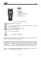
M70 4. OPERATING INSTRUCTIONS 4.1. INSTRUMENT - DESCRIPTION CAPTION: 1. 2. 3. 4. 5. 6. 7. 8. Inputs Inputs Display ON/OFF key LOCK key ZERO and backlight key GO key FUNC HOLD key Fig. 1: Instrument description key to switch on/off the instrument LOCK key to select the continuous mode measurement and to set the insulation measurement time ZERO key to calibrate the cables being used key to on and off the backlight GO GO key to start a measurement ARROW keys to select measurements 4.1.1.
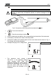
M70 4.2. : DC VOLTAGE MEASUREMENT CAUTION The maximum input voltage is 550+10%V. Don’t try to measure higher voltages to avoid risks of electrical shocks or serious damages to the instrument. Fig. 2: Connection of the instrument’s terminals during 1. Turn on the instrument 2. Press the arrow keys to select test 3. Insert the black and red cables in the corresponding input terminals of the instrument 4. If necessary, insert the croco clips on the test probes 5.
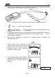
M70 4.3. : AC VOLTAGE MEASUREMENT CAUTION The maximum input voltage is 550+10%V. Don’t try to measure higher voltages to avoid risks of electrical shocks or serious damages to the instrument. Fig. 3: Connection of the instrument’s terminals during 1. Turn on the instrument 2. Press the arrow keys to select test 3. Insert the black and red cables in the corresponding input terminals of the instrument 4. If necessary, insert the croco clips on the test probes 5.
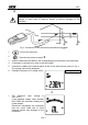
M70 4.4. : RESISTANCE MEASUREMENT AND CONTINUITY TEST CAUTION Before taking resistance measurements make sure that the circuit under test is not powered and that eventual condensers are discharged. The measured value is out of accuracy if an input voltage is present. Fig. 4: Connection of the instrument’s terminals during 1. Turn on the instrument 2. Press the arrow keys to select test 3. Insert the black and red cables in the corresponding input terminals of the instrument 4.
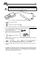
M70 2. Short-circuit the cable ends with each other as shown in Fig. 5 making sure that the metallic parts of test probes and crocodiles are in good touch Fig. 5: Connection of the instrument’s terminals during calibration procedure 3. GO 4. MODE PEAK Press GO to perform the measurement Press and hold ZERO key for 2s. The instrument resets the resistance of the cables, the symbol ZERO is displayed 5.
M70 4.5. Lo: CONTINUITY TEST ON EARTH, PROTECTIVE AND EQUALIZING POTENTIAL CONDUCTORS The measurement is performed with a test current higher than 200mA (R<5Ω) and open circuit voltage ranging from 4 to 24V DC according IEC/EN 61557-4 and VDE 0413 part 4. CAUTION Before taking resistance measurements make sure that the circuit under test is not powered and that eventual condensers are discharged. The measured value is out of accuracy if an input voltage is present. Fig.
M70 4.5.1. "ZERO" mode 1. Any addition or replacement of cables, extensions and croco clips nullify the previous calibration and make necessary a new calibration before performing further measurements. Therefore the instrument must be calibrated in the same conditions at which it will operate during measurements 2. Short-circuit the cable ends with each other as shown in Fig. 7 making sure that the metallic parts of test probes and crocodiles are in good touch Fig.
M70 4.6. M: INSULATION RESISTANCE MEASUREMENT TEST VOLTAGE 250V, 500V, 1000V DC The measurement is performed according to IEC/EN61557-2 and VDE 0413 part 1. CAUTION Before performing the insulation test make sure that the circuit under test is not energized and all relative loads are disconnected. The insulation measurement requires particolar care and attention to avoid providing wrong test results and causing damages to third parties.
M70 CAUTION The message on the display means that the instrument is discharging eventual capacitors. During this phase never disconnect nor touch test leads. 8. At the end of the test the instrument automatically discharge eventual capacitors and parasite capacitances present among the conductors involved in the measurement 9. At the end of the test a screen similar to this is displayed Nominal test voltage value Resistance value 10.
M70 5. MAINTENANCE 5.1. GENERAL This is a precision instrument. Strictly follow the instructions for use and storage reported in this manual to avoid any possible damage or danger during use. Do not use this tester under unfavorable conditions of high temperature or humidity. Do not expose to direct sunlight. Be sure to turn off the tester after use.
M70 6. TECHNICAL SPECIFICATIONS 6.1. CHARACTERISTICS Accuracy is indicated as [%reading + (digit number*resolution)] at 23°C±5°, RH <70%. DC Voltage Range 0.1 600.0V Resolution 0.1mV Accuracy (0.5 rdg + 1 dgt) Input impedance 3M Overload protection 605V AC max RMS Input impedance Overload protection 3M 605V AC max RMS AC Voltage Range Resolution 0.1 600.0V 0.1mV Max crest factor: Accuracy (40 ÷ 500Hz) (0.8 rdg + 4 dgt) 2 Resistance and Test Continuity Range Resolution 0.0 199.
M70 6.1.1. Electrical Conversion: Display refreshing rate: 6.1.2. Safety standards The instrument complies with: Insulation: Pollution level: Max height of use: Measurement category: 6.1.3. General specifications Mechanical features Dimensions (L x W x H): Weight (batteries included): Power supply Battery type: Low battery indication: Battery life: Display Features: 6.2. ENVIRONMENT 6.2.1.
M70 7. SERVICE 7.1. WARRANTY CONDITIONS This instrument is guaranteed against material or production defects, in accordance with our general sales conditions. During the warranty period the manufacturer reserves the right to decide either to repair or replace the product. Should you need for any reason to return back the instrument for repair or replacement take prior agreements with the local distributor from whom you bought it.