ENGLISH User manual © Copyright HT ITALIA 2012 Release EN 1.
HT9021 Contents: 1. SAFETY PRECAUTIONS AND PROCEDURES .......................................................... 2 1.1. 1.2. 1.3. 1.4. 2. GENERAL DESCRIPTION ........................................................................................... 4 2.1. 2.2. 3. TRMS and Mean value measuring instruments ................................................................ 4 True Root Mean Square value and Crest Factor definitions ............................................. 4 PREPARATION FOR USE .......
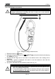
HT9021 1. SAFETY PRECAUTIONS AND PROCEDURES This clamp complies with IEC/EN61010-1. For your own safety and in order to avoid damaging the instrument, you’re recommended to keep to the instructions contained in this manual and read carefully all the notes preceded by the symbol . Take extreme care for the following conditions while measuring: • Do not measure voltage or current in humid or wet environment.
HT9021 1.2. DURING USE Always keep to the instructions contained in this manual. CAUTION Non compliance with the CAUTIONs and/or the instructions may damage the tester and/or its components or injure the operator. • • • • • • • Before changing the switch position, take off the clamp jaw from the tested conductor or the electrical circuit in order to avoid any accident When the clamp is connected to the circuits to be tested, never touch unused terminals When testing resistors, do not add voltage.
HT9021 2. GENERAL DESCRIPTION HT9021 meter can perform the herewith measurements: • • • • • • • • • DC and AC TRMS Voltage up to 1000V DC and AC TRMS Current up to 1000A Resistance and continuity test with buzzer Capacitance Frequency with test lead and jaws Duty cycle Diode test Temperature with type K probe AC voltage detection with and without contact with integrated sensor Each parameter can be selected by rotating the 8 positions switch. To abilitate the hold function the HOLD key is available.
HT9021 3. PREPARATION FOR USE 3.1. INITIAL The tester has been checked from a mechanical and electrical point of view before shipment. Every care has been taken to make sure that the instrument reaches you in perfect conditions. However, it’s advisable to make a rapid check in order to detect any damage which may have occurred in transit. Should this be the case, enter immediately the usual claims with the carrier. Make sure that all the accessories listed in § 6.3 are contained in the package.
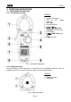
HT9021 4. OPERATING INSTRUCTIONS 4.1. INSTRUMENT DESCRIPTION 4.1.1. Command description LEGEND: 1. Inductive clamp jaw 2. LED for AC voltage detection 3. Jaw trigger 4. Function selector 5. HOLD / key 6. MODE, MAX/MIN, Hz%, PEAK/REL function keys 7. LCD display CAP Temp input 8. VΩ jack 9. COM input jack Fig. 1: Instrument description 4.1.2. Alignment marks Put the conductor within the jaws on intersection of the indicated marks as much as possible (see Fig.
HT9021 4.2. FUNCTION KEY DESCRIPTION 4.2.1. H key By pushing “H” key the parameter measured value is frozen on the display and the symbol ”HOLD” appears on it. This mode is disabled by pushing “H” key or moving the rotary switch. 4.2.2. key Keep pressed the “H” key for the backlight activation. This light could help the operator reading the display while he’s measuring in dark sites. For sake of battery saving after 10 seconds the light is automiatically switched off. 4.2.3.
HT9021 4.3. FUNCTIONS OF ROTARY SWITCH DESCRIPTION 4.3.1. AC Voltage measurement CAUTION Maximum input for AC Voltage measurements is 1000Vrms. Do not take any voltage measurement exceeding this limit in order not to risk electrical shock or damaging the tester Fig. 3: Taking AC voltage measurements 1. Approach the meter closest to AC source and note the turn on of red LED which is placed to the bottom of clamp jaws (see Fig. 1 – part 2) which detect the AC voltage 2. Rotate the switch on position 3.
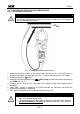
HT9021 4.3.2. DC Voltage measurement CAUTION Maximum input for DC Voltage measurements is 1000V. Do not take any voltage measurement exceeding this limit in order not to risk electrical shock or damaging the tester. Fig. 4: Taking DC voltage measurements 1. Rotate the switch on position 2. Insert the red test lead plug into VΩ CAP Temp jack and the black test lead plug into COM jack (Fig. 4) 3. Connect the two long ends of test leads to the desired circuit, then reading will be displayed 4. When “O.L.
HT9021 4.3.3. Resistance measurement CAUTION Before taking any in circuit resistance measurement, remove power from the circuit to be tested and discharge all the capacitors. Fig. 5: Taking Resistance measurement 1. Rotate the switch on Ω CAP position 2. Insert the red test lead plug into VΩ CAP Temp jack and the black test lead plug into COM jack (Fig. 5) 3. Connect the two long ends of test leads to the desired circuit, then reading will be displayed 4. When “O.L.
HT9021 CAUTION Before taking any in circuit resistance measurement, remove power from the circuit to be tested and discharge all the capacitors. Fig. 6: Taking Continuity test and Diode test 1. Rotate the switch on Ω CAP position symbol is shown at display 2. Pushing MODE key and select continuity test. The 3. Insert the red test lead plug into VΩ CAP Temp jack and the black test lead plug into COM jack and perform continuity test on the object under test (see Fig. 6 – left side).
HT9021 4.3.5. Capacitance measurement CAUTION When testing in-circuit capacitors, turn off the power of the circuit to be tested and discharge all the capacitors Fig. 7: Taking Capacitance measurement 1. Rotate the switch on Ω CAP position 2. Pushing MODE key and select capacitance test. The “nF” symbol is shown at display 3. Insert the red test lead plug into VΩ CAP Temp jack and the black test lead plug into COM jack (Fig. 7) 4.
HT9021 4.3.6. Temperature measurement CAUTION Do not allow the temperature sensor to contact a surface that is energized above 30 V RMS or 60 V DC, such voltages pose a shock hazard Fig. 8: Taking Temperature measurement 1. Rotate the switch on Temp position 2. Pushing MODE key and select the kind of measure. “°C” or “°K” symbols are shown at display respectively for Celsius or Farheneit temperature measurements 3.
HT9021 4.3.7. AC and DC Current measurement CAUTION Make sure that all the test leads are disconnected from the meter terminals for current measurement. Fig. 9: Taking AC and DC current measurements 1. Rotate the switch on 60A , 600A or 1000A position 2. Pushing MODE key and select the kind of measure “AC” or “DC” 3.
HT9021 4.3.8. Frequency and Duty cycle measurement CAUTION • On frequency test with test leads the maximum input for AC Voltage measurements is 1000Vrms. Do not take any voltage measurement exceeding this limit in order not to risk electrical shock or damage the tester • On frequency test with jaws make sure that all the test leads are disconnected from the meter terminals for current measurement. Fig.
HT9021 5. MAINTENANCE 5.1. GENERAL INFORMATIONS 1. This digital clamp meter is a precision instrument. Whether in use or in storage, please do not exceed the specification requirements to avoid possible damages or dangers. 2. Do not place this meter at high temperatures or humidity or expose it to direct sunlight. 3. Be sure to turn off the meter after use.
HT9021 6. TECHNICAL SPECIFICATIONS 6.1. CHARACTERISTICS Accuracy is calculated as [% rdg + (number of dgt) x resolution]. It is referred to the following reference conditions: 18°C ÷ 28°C (65°F ÷ 83°F), < 75%RH DC Voltage (Autorange) Range Resolution Accuracy Input impedance Overload protection 600.0mV 6.000V 60.00V 600.0V 1000V 0.01mV 0.001V 0.01V 0.1V 1V ±(1.
HT9021 Capacitance (Autorange) Range 40.00nF 400.0nF 4.000µF 40.00µF 400.0µF 4000µF Resolution 0.01nF 0.1nF 0.001µF 0.01µF 0.1µF 1µF Accuracy ±(3.5%rdg+40dgt) Overload protection ±(2.5%rdg+5dgt) 600VDC/ACrms ±(5.0%rdg+5dgt) Diode test Range Test current 0.9mA typical Open voltage 2.8VDC Frequency with test leads (Autorange) Range 99.99Hz 999.9Hz 9.999kHz 60.00kHz Resolution 0.01Hz 0.1Hz 0.001kHz 0.01kHz Accuracy Sensitivity Overload protection ±(1.
HT9021 Supply Battery type: Low battery indication: Battery life: AutoPowerOff: 1 battery 9V NEDA 1604 IEC 6F22 JIS 006P. “ ” is displayed when the battery level is low about 200 hours after 15 minutes of idleness Display Characteristics: 4 LCD (max 6000 counts), decimal point, unit symbol indication, bargraph and backlight 2 times/sec TRMS Sample rate: Conversion mode: 6.2. ENVIRONMENTAL CONDITIONS 6.2.1.
HT9021 7. SERVICE 7.1. WARRANTY CONDITIONS This equipment is guaranteed against material faults or production defects, in accordance with the general sales conditions. During the warranty period (one year), faulty parts may be replaced. The manufacturer reserves the right to decide either to repair or replace the product. In case of returning of the instrument, all transport charges must be paid by the customer.