ENGLISH User Manual Copyright HT ITALIA 2013 Release EN 1.
HT8100 Table of contents: 1. PRECAUTIONS AND SAFETY MEASURES ............................................................... 2 1.1. Preliminary instructions ..................................................................................................... 2 1.2. During use ......................................................................................................................... 3 1.3. After use ................................................................................................
HT8100 1. PRECAUTIONS AND SAFETY MEASURES The instrument has been designed in compliance with directive IEC/EN61010-1 relevant to electronic measuring instruments. For your safety and in order to prevent damaging the instrument, please carefully follow the procedures described in this manual and read all notes preceded by the symbol with the utmost attention.
HT8100 1.2. DURING USE Please carefully read the following recommendations and instructions: CAUTION Failure to comply with the Caution notes and/or Instructions may damage the instrument and/or its components or be a source of danger for the operator. Before activating the rotary switch, disconnect the test leads from the circuit under test. When the instrument is connected to the circuit under test, do not touch any unused terminal. Avoid measuring resistance if external voltages are present.
HT8100 2.
HT8100 3. PREPARATION FOR USE 3.1. INITIAL CHECKS Before shipping, the instrument has been checked from an electric as well as mechanical point of view. All possible precautions have been taken so that the instrument is delivered undamaged. However, we recommend generally checking the instrument in order to detect possible damage suffered during transport. In case anomalies are found, immediately contact the forwarding agent.
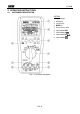
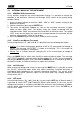
HT8100 4. OPERATING INSTRUCTIONS 4.1. INSTRUMENT DESCRIPTION CAPTION: 1. Auto Backlight 2. LCD display 3. Function keys 4. MODE key 5. Rotary selector switch 6. Input terminal COM 7. Input terminal mA 8. Input terminal HzV 9. Input terminal A Fig.
HT8100 4.2. DESCRIPTION OF FUNCTION KEYS The following § describes the functions of the different keys. When pressing a key, the display shows the symbol of the activated function and the buzzer sounds. 4.2.1. A-HOLD and REL keys Pressing the A-HOLD key in any function, except for the current generation function and diode test function, keeps the value of the measured quantity shown on the display. The message “HOLD” appears on the display.
HT8100 4.3. INTERNAL MODES OF THE INSTRUMENT 4.3.1. MIN/MAX/AVG measurement In any function, except for the current generation function, it is possible to activate the detection of the Maximum, Minimum and Average (AVG) values of the quantity being tested as follows: 1. Use the 4-arrow selector to select the “MAX”, “MIN” or “AVG” symbols flashing at the bottom of the display. 2. Confirm selection by pressing the ENTER key. 3.
HT8100 4.3.5. STORE and RECALL modes For each measuring function, except for the current generation function, it is possible to save the displayed value in the instrument’s memory and to recall the data saved on the display at any time. The instrument allows saving max. 100 pieces of data in the memory. Proceed as follows: Data saving 1. Select the “STORE” symbol flashing on the display, using the 4-arrow selector located on the front panel of the instrument. 2.
HT8100 4.3.7. Output DC current generation The “OUTPUT” section of the function selector switch defines the possibility of generating an output DC current with the instrument, considering the selectable measuring ranges 020mA or 4-20mA. The instrument may operate in the following modes: DC current source DC current generation (see § 4.4.7). Simulation simulation of a transducer in a current loop with auxiliary power supply (see § 4.4.
HT8100 4.4. MEASURING OPERATIONS 4.4.1. DC Voltage measurement CAUTION The maximum input DC voltage is 1000 V. Do not measure voltages exceeding the limits given in this manual. Exceeding voltage limits could result in electrical shocks to the user and damage to the instrument. Fig. 2: Use of the instrument for DC voltage measurement 1. Select positions V or mV 2. Press the MODE key for manually selecting “DC” measurement. 3. Use the RANGE key for manually selecting the measuring range (see § 4.2.
HT8100 4.4.2. AC Voltage and Frequency measurement CAUTION The maximum input AC voltage is 1000Vrms. Do not measure voltages exceeding the limits given in this manual. Exceeding voltage limits could result in electrical shocks to the user and damage to the instrument. Fig. 3: Use of the instrument for AC voltage measurement 1. Select positions V or mV 2. Press the MODE key for manually selecting “AC” or “AC+DC” measurement (see § 4.3.3) or press the HFR key for “HFR” measurement (see § 4.3.4). 3.
HT8100 4.4.3. DC Current measurement CAUTION The maximum input DC current is 1A. Do not measure currents exceeding the limits given in this manual. Exceeding current limits could result in electrical shocks to the user and damage to the instrument. Fig. 4: Use of the instrument for DC current measurement 1. 2. 3. 4. 5. 6. 7. 8. 9. Cut off power supply from the circuit to be measured. Select position A or mA (for measuring currents <50mA). Press the MODE key for manually selecting “DC” measurement.
HT8100 4.4.4. AC Current and Frequency measurement CAUTION The maximum input AC current is 1A. Do not measure currents exceeding the limits given in this manual. Exceeding current limits could result in electrical shocks to the user and damage to the instrument. Fig. 5: Use of the instrument for AC current measurement 1. Cut off power supply from the circuit to be measured. 2. Select position A or mA (for measuring currents <50mA). 3.
HT8100 4.4.5. Resistance measurement and Continuity test CAUTION Before attempting any resistance measurement, cut off power supply from the circuit to be measured and make sure that all capacitors are discharged, if present. Fig. 6: Use of the instrument for resistance measurement and continuity test 1. Select the position. The symbol “M” is shown on the display 2. Use the RANGE key for manually selecting the measuring range (see § 4.2.4) or use Autorange selection.
HT8100 4.4.6. Diode test CAUTION Before attempting any diode test, cut off power supply from the circuit to be measured and make sure that all capacitors are discharged, if present. Fig. 7: Use of the instrument for diode test position Select the Press the MODE key to select the Diode Test. The symbol “ ” is shown on the display Insert the red cable into input lead HzV and the black cable into input lead COM.
HT8100 4.4.7. DC current generation CAUTION The maximum output DC current generated by the instrument is 24mA with internal battery voltage > 4.5VDC. Fig. 8: Use of the instrument for DC current generation 1. Switch on the instrument by pressing and holding the RANGE key to select the measuring range 0-20mA or 4-20mA. 2. Select the position mA in case of programmable DC current generation or position mA for DC current generation with automatic ramp. 3.
HT8100 4.4.8. Simulation of a transducer CAUTION In this mode, the instrument provides an adjustable output current up to 24mADC. It is necessary to provide an external power supply with voltage between 6V and 48VDC in order to adjust current. Fig. 9: Use of the instrument for simulating a transducer 1. Switch on the instrument by pressing and holding the RANGE key to select the measuring range 0-20mA or 4-20mA. 2.
HT8100 4.4.9. Measuring output DC current from external transducers (Loop) CAUTION In this mode, the instrument provides an output voltage > 24VDC / 20mA, capable of supplying an external transducer and allowing measuring loop current at the same time. Fig. 10: Use of the instrument for measuring output DC current from external transducers 1. Cut off power supply from the circuit to be measured. 2. Select the position mA LOOP POWER. The message “LOOP POWER” is shown on the display.
HT8100 5. MAINTENANCE CAUTION 5.1. Only expert and trained technicians should perform maintenance operations. Before carrying out maintenance operations, disconnect all cables from the input terminals. Do not use the instrument in environments with high humidity levels or high temperatures. Do not expose to direct sunlight. Always switch off the instrument after use.
HT8100 6. TECHNICAL SPECIFICATIONS 6.1. TECHNICAL CHARACTERISTICS Accuracy indicated as [% reading + (number of dgt * resolution)] at 23°C±5°C, <80%RH DC Voltage Range Resolution Accuracy 50.000mV 500.00mV 5.0000V 50.000V 500.00V 1000.0V 0.001mV 0.01mV 0.0001V 0.001V 0.01V 0.1V (0.05%rdg+30dgt) (0.
HT8100 Resistance Range Resolution Accuracy Output current Protection against overcharge 500.00 5.0000k 50.000k 500.00k 5.0000M 50.00M (*) 0.01 0.0001k 0.001k 0.01k 0.0001M 0.01M (0.2%rdg+30dgt) 1mA 100µA 10µA 1µA 100nA 10nA 1000VDC/ACrms (0.2%rdg+10dgt) (0.5%rdg+10dgt) (1.0%rdg+10dgt) (2.0%rdg+10dgt) (*) Slight instability < 20 dgt Maximum open-circuit voltage: approx 3.5V Continuity test Range Accuracy Buzzer Open-circuit voltage 500.00 (0.1%rdg+30dgt) <30 circa 3.
HT8100 Generated DC current – Output ramp Ramp type Description Action Slow linear ramp Passage from 0% 100% 0% in 40s Quick linear ramp Passage from 0% 100% 0% in 20s Slow step ramp 0% 100% 0% with ramps of 15s Quick step ramp 0% 100% 0% with ramps of 5s Output voltage: 32.0VDC: Output voltage accuracy: ±5.0% of reading Power supply: battery level > 4.
HT8100 6.2. ENVIRONMENT 6.2.1. Environmental conditions for use Reference temperature: 23° ± 5°C (73 ± 41°F) Operating temperature/humidity: -10°C ÷ 30°C (14°F ÷ 86°F), <85%RH 30°C ÷ 40°C (86°F ÷ 104°F), <75%RH 40°C ÷ 50°C (104°F ÷ 122°F), <45%RH Storage temperature: -20° ÷ 60°C (-4 ÷ 140°F) (batteries not inserted) Storage humidity: <80%RH This instrument satisfies the requirements of Low Voltage Directive 2006/95/EC (LVD) and of EMC Directive 2004/108/EC 6.3. ACCESSORIES 6.3.1.
HT8100 7. SERVICE 7.1. WARRANTY CONDITIONS This instrument is warranted against any material or manufacturing defect, in compliance with the general sales conditions. During the warranty period, defective parts may be replaced. However, the manufacturer reserves the right to repair or replace the product. Should the instrument be returned to the After-sales Service or to a Dealer, transport will be at the Customer’s charge. However, shipment will be agreed in advance.