ENGLISH User’s manual © Copyright HT ITALIA 2012 Release EN 1.
HT712 Content: 1. SAFETY PRECAUTIONS AND PROCEDURES ...................................................................... 2 1.1. Preliminary ........................................................................................................................ 2 1.2. During use ......................................................................................................................... 3 1.3. After use ...........................................................................................
HT712 1. SAFETY PRECAUTIONS AND PROCEDURES This instrument complies with EN 61010-1 concerning electronic measuring instruments. For your own safety and to avoid damaging the instrument follow the procedures described in this instruction manual and read carefully all notes preceded by this symbol . When taking measurements: • avoid doing that in humid or wet places - make sure that humidity is within the limits indicated in section “environmental conditions”.
HT712 1.2. DURING USE CAUTION An improper use may damage the instrument and/or its components or injure the operator. • • • • Before changing the range, first disconnect the test leads from the circuit under test in order to avoid any accident. When the instrument is connected to circuits never touch an unused terminal. When measuring resistors do not add any voltage. Although there is a protection circuit, excessive voltage would still cause malfunctioning.
HT712 2. GENERAL DESCRIPTION The instrument performs the following measurements: ● ● ● ● ● ● ● ● DC and AC TRMS voltage AC voltage with 1 test lead Frequenza Frequency with 1 test lead Phase sequence test Phase conformity test Resistance Continuity test selectable by means of a 5-position rotary selector. Three function keys are also available. The selected measurement is displayed with indication of active functions.
HT712 3. PREPARATION TO USE 3.1. INITIAL This instrument was checked both mechanically and electrically prior to shipment. All possible cares and precautions were taken to let you receive the instrument in perfect conditions. Notwithstanding we suggest you to check it rapidly (eventual damages may have occurred during transport). Make sure that all standard accessories mentioned in paragraph 6.3.1 are included.
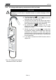
HT712 4. OPERATING INSTRUCTIONS 4.1. INSTRUMENT - DESCRIPTION 4.1.1. Front panel LEGEND: Fig. 1: Instrument description 1. Test probe (accessory) 2. V+/Ω input terminal 3. DISP key 4. HOLD key 5. Metallic pad 6. COM input terminal 7. Rotary selector 8. MEAS key 9. LCD 4.2. FUNCTION KEYS Once pressed, the relevant symbol appears on the display and the buzzer beeps. Every time the selector is rotated all functions activated by means of the function keys are cancelled. Fig. 2: Function keys 4.2.1.
HT712 4.4. MEASUREMENTS - DESCRIPTION 4.4.1. DC voltage measurement CAUTION The maximum input for DC voltage is 600V. Don’t try to measure higher voltages to avoid risks of electrical shocks or serious damages to the instrument. 1. Turn the selector on . 2. Insert the black test lead in the COM jack and the red probe in the V+/Ω jack (Fig. 3). 3.
HT712 4.4.2. AC voltage and frequency measurement with 2 test leads CAUTION The maximum input for AC voltage is 600V. Don’t try to measure higher voltages to avoid risks of electrical shocks or serious damages to the instrument. 1. Turn the selector on . 2. Insert the black test lead in the COM jack and the red probe in the V+/Ω jack (Fig. 4). 3. Connect the red probe and the black test lead to the poles of the circuit under test; the voltage value will be displayed (automatic range detection).
HT712 4.4.3. AC voltage and frequency measurement with 1 test leads CAUTION The maximum input for AC voltage is 600V. Don’t try to measure higher voltages to avoid risks of electrical shocks or serious damages to the instrument. L1 1. Turn the selector on . 2. Insert the red probe in the V+/Ω jack (Fig. 5). 3. Keep the instrument gripped correctly by touching the metallic pad with a finger. 4.
HT712 4.4.4. Phase sequence test and phase conformity test CAUTION The maximum input for AC voltage is 600V. Don’t try to measure higher voltages to avoid risks of electrical shocks or serious damages to the instrument. L1 1. Turn the selector on . 2. Keep the instrument gripped correctly (Fig. 6) by touching the metallic pad with a finger. 3. The symbol "L1" appearing on the display means that the instrument is ready to perform the first measurement.
HT712 8. Disconnect the test probe to the L1 phase cable (at this point the “PH” disappears). The symbol "L2" means that the instrument is waiting for the second phase to be measured. For the phase rotation test: 9. Connect the test probe to the L2 phase cable or simply lean it to the insulated cable under test. For the phase concordance test: 9. Connect the test probe to the L1 phase cable of the second three phase system or simply lean it to the insulated cable under test. 10.
HT712 4.4.5. Resistance measurement and continuity test CAUTION Before taking in circuit resistance measurements, remove power from the circuit being tested and discharge all capacitors. 1. Turn the selector on . 2. Insert the black test lead in the COM jack and the red probe in the V+/Ω jack (Fig. 7). 3. Connect the test lead to the circuit under test; the resistance value will be displayed (automatic range detection). 4. Should you get the message "O.
HT712 5. MAINTENANCE 5.1. GENERAL INFORMATION This is a precision instrument. To guarantee its performances be sure to use it or keep it stored on suitable environmental conditions. Do not expose it to high temperatures or humidity or direct sunlight. Be sure to turn it off after use. If you expect not to use the instrument for a long period remove batteries to avoid leakages of battery liquid which could damage the its inner components. 5.2.
HT712 6. TECHNICAL SPECIFICATIONS 6.1. TECHNICAL FEATURES The accuracy is indicated as [% of reading + number of digits]. It is referred to the following environmental conditions: temperature 23°C ± 5°C, relative humidity < 70%. DC voltage measurement Range Resolution Accuracy Input impedance 1.5 ÷ 600.0V 0.1V ±(0.8%rdg+1dgt) 10MΩ AC voltage measurement with 2 test leads Accuracy Range Resolution (40.0 ÷ 69.9Hz) 0.1V 1.5 ÷ 600.0V ±(1.
HT712 6.1.1. Electrical Conversion Display refreshing rate TRMS 3 times per second 6.1.2. Safety The instrument complies with Insulation Pollution degree Overvoltage category For inside use, max height EN 61010-1 Class 2, Double insulation 2 CAT IV 600 V 2000m; 6561ft 6.1.3. General data Mechanical characteristics Dimensions Weight (including batteries) Power supply Battery type Indication of low batteries Battery life: Display Type 6.2. ENVIRONMENT 6.2.1.
HT712 7. SERVICE 7.1. WARRANTY CONDITIONS This instrument is guaranteed for one year against material or production defects, in accordance with our general sales conditions. During the warranty period the manufacturer reserves the right to decide either to repair or replace the product. Should you need for any reason to return back the instrument for repair or replacement take prior agreements with the local distributor from whom you bought it.