
User guide


HT710
EN - 11
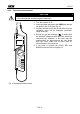
4.4.6. Diode test
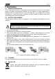
CAUTION
Before taking in circuit diode test, remove power from the circuit being
tested and discharge all capacitors.
R
A
N
G
E
H
O
L
D
Fig. 8: Diode test
1. Turn the selector on .
2. Insert the black test lead in the COM jack and the red
probe in the V+/Ω jack (Fig. 7).
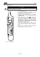
3. Connect the test lead to the circuit under test; the
resistance value will be displayed (automatic range
detection).
4. Should you get the message "
O.L
" it means that the
detected voltage exceeds the limits which the
instrument can measure or that the above described
connections are inverted.