ENGLISH User manual Copyright HT ITALIA 2012 Release EN 2.
HT2055 Table of Contents: 1 PRECAUTIONS AND SAFETY MEASURES .............................................................................. 2 1.1 1.2 1.3 1.4 Preliminary instructions ........................................................................................................................ 2 During use ............................................................................................................................................ 3 After use ..........................................
HT2055 1 PRECAUTIONS AND SAFETY MEASURES The instrument has been designed in compliance with standards IEC/EN61557-1 and IEC/EN61010-1 regarding electronic measuring instruments. CAUTION For the operator’s safety and to prevent damaging the instrument, follow the procedures described in this manual and carefully read all notes preceded by the symbol .
HT2055 1.2 DURING USE Carefully read the following recommendations and instructions: CAUTION Failure to observe the warnings and/or instructions may damage the instrument and/or its components or generate a danger for the operator Before selecting a new function, disconnect the measuring probes from the circuit When the instrument is connected to the circuit under test, never touch any unused lead The auxiliary current probe can be subject to a higher voltage.
HT2055 2 GENERAL DESCRIPTION The instrument HT2055 you purchased grants accurate and reliable measurements as well as the utmost safety provided it is used in compliance with the indications given in this manual. Thanks to a new concept development it ensures double insulation and, consequently, compliance with the requirements of overvoltage category IV.
HT2055 3 PREPARATION FOR USE 3.1 INITIAL INSPECTIONS Before shipment, the instrument’s electronics and mechanics were inspected. All possible precautions were taken to permit delivery of instrument free of damage. However, we recommend generally inspecting the instrument in order to detect any damage suffered during transport. Should you detect any anomalies, immediately contact the forwarding agent or the dealer. Moreover, we recommend checking that the package contains all parts listed in § 11.3.
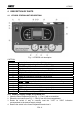
HT2055 4 DESCRIPTION OF PARTS 4.1 HT2055S STATION UNIT DESCRIPTION Fig. 1: HT2055S unit description CAPTION: 1 2 3 4 5 6 7 8 9 10 11 – 12 13 14 15 16 17 Protection fuse on mains (see § 11.
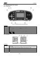
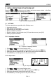
HT2055 4.2 DESCRIPTION OF TEST LEADS 4.2.1 Front view Fig. 2: HT2055M unit front view description CAPTION: 1 2 3 4 5 6 7-8 ESC key to return at previous screen MEM key for access to internal memory (see § 8) , , , arrow keys and TEST key to activation measurements Backlight key LCD display ON/OFF key to switch the instrument ON or OFF and keys for function selection and parameter settings 4.2.2 Top view Fig. 3: HT2055M unit top view description CAPTION: 1 2 3 4 5 Test connector.
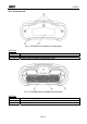
HT2055 4.2.3 Backside view Fig. 4: HT2055M unit backside view description CAPTION: 1 2 3 Battery compartment cover Safety information label Fixing screws for battery compartment cover Fig. 5: HT2055M battery compartment description CAPTION: 4 5 6 Serial number label Battery cells (6x1.
HT2055 5 INITIAL OPERATIONS WITH HT2055M UNIT Press the or function keys to display the below screens relative to the Step Voltage, Contact Voltage and Settings (see Fig. 6) Fig. 6: Screens of general menu 5.1 SETTINGS The below operations are possible within Settings menu: Language selection Help screens on connections Syncronizing with the station unit HT2055S Restore of default conditions Recall at display of saved results (see § 8.2) and clear memory (see § 8.
HT2055 5.1.3 Synchronization Selecting this option will allow to upload different data from the station unit to the meter unit. The possible options are: Synchronization of the actual time/date and the generated current Uploading of test current results for Step / Contact voltage calculation Uploading of earth resistance and ground resistivity results Fig. 9: Synchronization screen 1. 2. 3. 4.
HT2055 5.1.4 Default settings This section permits to restore the default value (factory) of measurement parameters and limits set on the instrument Fig. 10: Initial settings screen 1. 2. 3. 4.
HT2055 6 INITIAL OPERATIONS WITH HT2055S UNIT Press the or function keys to display the below screens relative to the earth/resistivity measurements and Settings (see Fig. 12) Fig. 12: Screens of general menu 6.1 SETTINGS The below operations are possible within Settings menu: Language selection (see § 5.1.1) Restore of default conditions Setting power of current generator Setting of alarm conditions when switching off test current Recall at display of saved results (see § 8.
HT2055 6.1.2 Setting output power This section permits to set the output power of current generator by selecting the percentages: 10%, 25%, 50%, 75% and 100% Fig. 14: Output power generator setting screen 1. 2. 3. 4.
HT2055 6.2 ADJUST CONTRAST OF DISPLAY key. The following screen is shown: 1. Press the 2. Use the or keys to reduce or increase the contrast percentage of display 3. Press the TEST key to confirm the operation or the ESC key to exit from this function 6.3 HELP SCREENS screen to display the help screen correspondent to the selected function 1. Pressing 2. Use the or keys to select the other help screens 3. Press ESC key to exit and go back to the previous screen 6.
HT2055 7 HOW TO PERFORM THE MEASUREMENTS 7.1 THEORY OF STEP/CONTACT VOLTAGE MEASUREMENTS An earth electrode / grid depleted into ground has a certain resistance, depending on its size, surface (oxides on the metal surface) and the soil resistivity around the electrode. The earth resistance is not concentrated in one point but is distributed around the electrode. Correct connection of exposed conductive parts assures that the voltage on them stays below dangerous level in case of a fault.
HT2055 7.2 STEP/CONTACT VOLTAGE MEASUREMENT The measurements of step/contact voltage are performed by a voltmeter with an internal resistance of 1k simulating the body resistance and with two weight probes of 25 kg each simulating feet. Alternatively it is possible to use two metal plates instead of weight probes on the ground where the operator stands. CAUTION During the measurement a test current is injected into the earth through an auxiliary probe.
HT2055 Fig. 17: Circuit scheme for step voltage measurement Fig. 18: Circuit scheme for contact voltage measurement Generation of test current 3 Switch on the station unit HT2055S 4 Use or keys and select the “CURRENT GEN.” screen (see Fig. 19) Fig.
HT2055 5 Press TEST key to activate the operation. The value of generated current is displayed. Check this value. CAUTION The output power is set automatically to its available maximum value (see § 6.1.2) Completely unwind measuring cable to avoid affecting test current value (coil impedance) Usually the resistance of auxiliary probe can affect the generated test current. The injected current can be increased by placing more probes in parallel.
HT2055 Perform step/contact voltage measurements 8 Use or keys and select the CONTACT VOLT or STEP VOLT measurements on the meter unit Fig. 21: Screens for step/contact voltage measurements 9 Use ,, and keys and perform the settings of the following test parameters: Igen Iflt Test current (manual setting considering the range 0.
HT2055 Synchronization between the units after the test (recommended) If the meter and station units were synchronized during the measurements they should be synchronized again after completing the tests. In this step the values of generated currents (measured with the station) are downloaded to the meter so automatically correcting the measured results previously stored and providing the correct value of step and contact voltages.
HT2055 7.3 EARTH RESISTANCE MEASUREMENT The earth resistance measurement is performed by the HT2055S station unit only by using the standard 3-wire method with two supplied auxiliary probes fitted at adequate distances from the earth system under test according to the Fig. 24 Fig. 24: Connection of instrument for earth resistance measurement 1 Place the station unit close to the earth system under test (distance max.
HT2055 5 Use or keys and select the EARTH RE measurement on the station unit. The following screen is displayed: Fig. 25: Main screen of earth resistance measurement 6 Press TEST key to perform the measurement. The result is displayed Fig.
HT2055 7.4 GROUND RESISTIVITY MEASUREMENT For the ground resistivity measurement the test current is injected through two current probes (C1/H and C2/E). The voltage probes S and ES must be placed between the current probes (equidistance ‘a’ between probes must be considered). Using different distances between the test probes means that the material is measured at different depths. By increasing the distance ‘a’ a deeper layer of ground material is measured (see Fig. 27) Fig.
HT2055 CAUTION When starting test the unit performs a preliminary check of the resistance values of current probe (Rc) and voltage probe (Rp) stopping the test if these values are assumed to be too high and giving the messages “Rc: >2.0k” and “Rp: >2.0k”. Decrease the resistance value wetting the ground close to the probes and/or connect more probes in parallel High noise currents and voltages in earth could affect the measurement results.
HT2055 8 OPERATION WITH MEMORY The measurement results, including associated parameters, can be saved inside the internal memories of station unit and meter unit.
HT2055 Measurement structure No.: 1 No.: 1 [13] > No.: 7/7 STEP VOLT Number of measurements associated to the selected location Number of measurements in the selected location [Number of measures in the selected location and sub-locations] Number of selected test / Number of all results saved in the selected location Type of measurement saved in the selected location 8.
HT2055 8.3 DELETE SAVED RESULTS The following operations are available: Deletion of all memory Deletion of data in single selected locations Deletion of generated currents (only for station unit) Deletion of internal memory 1 Selected the item “MEMORY CLEAR ALL MEMORY” inside settings menu (see § 5.1). The following screen is displayed Fig. 33: Deletion of internal memory 2 Press TEST key to confirm the operation.
HT2055 9 CONNECTION OF THE INSTRUMENT TO PC The saved data can be transferred to PC by using the TeraView software provided with instrument.
HT2055 8. Select the “Config COM Port…” command and click on the “AutoFind” button to start the automatic detection of the instrument (see Fig. 37) Fig. 37: Connection of the instrument to PC 9. The herewith message means a correct detection of meter by the PC Fig. 38: Correct detection of instrument 10. In case of meter detection failure by the PC it should be necessary to re-configure the “virtual” COM serial port associated with the USB driver previously installed.
HT2055 10 MAINTENANCE CAUTION During use and storage, carefully observe the recommendations listed in this manual in order to prevent possible damage or dangers during use Do not use the instrument in environments with high humidity levels or at high temperatures. Do not directly expose to sunlight. Always turn off the instrument after use. Never remove the front panel of the instrument. The instrument don’t need any particular maintenance 10.
HT2055 11 TECHNICAL SPECIFICATIONS The accuracy is calculated as [% rdg + (number of dgt) * resolution] at reference condition indicated in § 11.2 Step/Contact voltage measurement Measured voltage range 0.01 19.99mV 20.0 199.9mV 200 1999mV 2.00 19.99V 20.0 59.9V Resolution 0.01mV 0.1mV 1mV 0.01V 0.1V Calculated voltage range 0.0 199.9V 200 999V Resolution 0.1V 1V Accuracy (2.
HT2055 11.1 GENERAL CHARACTERISTICS Station unit HT2055S Power supply: Max. power consumption: Protection on mains: Safety of meter: Safety of accessories: Installation over 1kVAC: Earth/resistivity measurement: Italian guideline: Spanish guideline: Insulation: Measurement category: Pollution degree: Mechanical protection: 110V (±10%) or 230V AC (±10%), 50/60Hz 750VA 2x fuse T 6.
HT2055 11.2 ENVIRONMENT Reference temperature: Reference humidity: Operating temperature: Operating humidity: Storage temperature: Storage humidity: 10°C ÷ 30°C ; 50°F ÷ 86°F 35% ÷ 65%RH 0°C ÷ 40°C ; 32°F ÷ 104°F <85%HR -10°C ÷ 60°C ; 14°F ÷ 140°F <80%HR This instrument complies with the requirements of European Directive on low voltage 2006/95/EC (LVD) and of Directive EMC 2004/108/EC 11.
HT2055 12 SERVICE 12.1 WARRANTY CONDITIONS This instrument is warranted against any material or manufacturing defect, in compliance with the general sales conditions. During the warranty period, defective parts may be replaced. However, the manufacturer reserves the right to repair or replace the product. Should the instrument be returned to the After-sales Service or to a Dealer, transport will be at the Customer's charge. However, shipment will be agreed in advance.