ENGLISH User’s manual ©Copyright HT ITALIA 2007 Release EN 1.
HT4014-HT4016 CONTENTS: 1. SAFETY PRECAUTIONS AND PROCEDURES .............................................................2 1.1. Preliminary ............................................................................................................3 1.2. During Use ............................................................................................................3 1.3. After Use ...............................................................................................................3 1.4.
HT4014-HT4016 1. SAFETY PRECAUTIONS AND PROCEDURES This instrument is conforms to safety standard EN 61010, relating to electronic measuring instruments. For your own safety and that of the apparatus, you must follow the procedures described in this instruction manual and especially read all the notes preceded carefully. by the symbol WARNING If instrument is used in way don’t conform to prescriptions of this user’s manual, all considered safety protection maybe damaged.
HT4014-HT4016 1.1. PRELIMINARY • This apparatus has been designed for use in an environment of pollution degree 2. • It can be used for CURRENT, VOLTAGE and FREQUENCY measurements on installations of surge voltage category III up to 600 V, voltage between Phase and Earth (fixed installations) and for current measures up to 400A. Please refer to chapter 1.4 for information regard on overvoltage categories. • This meter is not available for non-sine wave AC signal.
HT4014-HT4016 1.4. DEFINITION OF MEASURING (OVERVOLTAGE) CATEGORY The norm EN 61010: Safety requirements for electrical equipment for measurement, control and laboratory use, Part 1: General requirements, defines what a measuring category, usually called overvoltage category, is. Circuits are divided into the following measurement categories: • • • • Measurement category IV is for measurements performed at the source of the low-voltage installation.
HT4014-HT4016 2. GENERAL DESCRIPTION This manual is referred to two models: HT4014 and HT4016; the difference between the models is fundamentally the capacity of the first to measure the frequency and of the latter to measure DC current and to perform relative measurements using the ZERO function. Where not expressly indicated the characteristics are common for both models. The apparatus can perform the following measurements: • AC current. • AC voltage. • DC voltage. • DC current (HT4016 only).
HT4014-HT4016 3. PREPARATION FOR USE 3.1. INITIAL This instrument has been checked mechanically and electrically before shipment. All precautions have been taken to assure that the instrument reaches you in perfect condition. However, it is advisable to carry out a rapid check in order to detect any possible damage, which might have occurred in transit. Check the packaging contained according to packaging list reported in paragraph 6.3.1. In case of discrepancies contact the dealer.
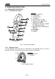
HT4014-HT4016 4. OPERATING INSTRUCTIONS 4.1. INSTRUMENT DESCRIPTION 4.1.1. Commands description LEGEND: 1. Inductive clamp jaw. 2. Safety guard. 3. Data HOLD key. 4. Jaw trigger. 5. Rotary selector functions. 6. Selection key Ω/ (HT4014); ZERO key (HT4016). 7. MAX/MIN key (HT4014); RANGE R-H / key (HT4016). 8. key (HT4014); MAX/MIN key (HT4016). 9. LCD display. 10. COM jack. 11. V/Ω jack. HT4018 Fig. 1: Instrument description 4.1.2.
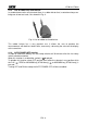
HT4014-HT4016 4.1.3. Use of rubber test leads holster In standard accessories of instrument there is a rubber holster that, inserted on clamp, can bring one of two test leads, like showed in Fig. 3. Fig. 3: Use of rubber test lead holster This rubber holster has a very practical use. It allows the user to perform the measurements with both test leads while, more easily, observing the value on the display at the same time. 4.1.4.
HT4014-HT4016 4.2. FUNCTION KEY DESCRIPTION key: range selection / backlight function (HT4016 only) 4.2.1. R-H / For R-H function: key less than 1 second, Manual range is activated. 1. Press R-H / 2. Press R-H / key more than 1 second, Manual range is disabled and Backlight is ON. 3. Press R-H / key for more than 1 second, Backlight is OFF and Manual range is activated. For function: 1. Press R-H / key more than 1 second, Backlight is ON; 2. Press R-H / key more than 1 second, Backlight is OFF.
HT4014-HT4016 4.3. DESCRIPTION OF ROTARY SWITCH FUNCTION 4.3.1. AC Voltage measurement WARNING Maximum input for AC Voltage measurements is 600V. Do not attempt to take any voltage measurement that exceeds the limits. Exceeding the limits could cause electrical shock and damage the clamp meter. Fig. 4: Use of clamp for AC voltage measures 1. Select the “V~”position of selector functions. 2. Insert the test leads into the jack, the red plug into V/Ω jack, and black plug into COM jack, like showed in Fig.
HT4014-HT4016 4.3.2. DC Voltage measurement WARNING Maximum input for DC Voltage measurements is 600V. Do not attempt to take any voltage measurement that exceeds the limits. Exceeding the limits could cause electrical shock and damage the clamp meter. Fig. 5: Use of clamp for DC voltage measures 1. Select the ““ V”position of selector functions. 2. Insert the test leads into the jack, the red plug into V/Ω jack, and black plug into COM jack, like showed in Fig. 5. 3.
HT4014-HT4016 4.3.3. AC Current measurement WARNING • Make sure that all the test leads are disconnected from the meter's terminals for current measurement. • When measuring current, any strong current nears or closes to the clamp jaws will affect the accuracy. • The instrument is not available for non-sine wave AC signal. Correct Incorrect Fig. 6: Use of clamp during AC current measurement 1. Select “~A” position. 2.
HT4014-HT4016 4.3.4. DC Current measurement (HT4016 only) WARNING • Make sure that all the test leads are disconnected from the meter's terminals for current measurement. • When measuring current, any strong current nears or closes to the clamp jaws will affect the accuracy. Current direction Correct Incorrect Current direction Fig. 7: Use of clamp during DC current measurement (HT4016 only). 1. Select “ A” position. 2. Check if the display shows zero in advance.
HT4014-HT4016 4.3.5. Resistance measurement WARNING Before taking any in circuit resistance measurement, remove power from the circuit being tested and discharge all the capacitors. Fig. 8: Use of clamp for resistance measures. 1. Select the function “Ω/ ” (HT4014 only) or the function “Ω” (HT4016 only). 2. Insert the test leads into the jack, the red plug into V/Ω jack, and black plug into COM jack, like showed in Fig. 8. 3. Insert the two long ends of test leads to the desired circuit.
HT4014-HT4016 4.3.6. Continuity Test WARNING Before taking any in circuit resistance measurement, remove power from the circuit being tested and discharge all the capacitors. Fig. 9: use of clamp for continuity measure 1. Select the Ω/ function (HT4014 only) or the “ ” function (HT4016 only). 2. Insert the test leads into the jack, the red plug into V/Ω jack, and black plug into COM jack, like showed in Fig. 9. 3. Insert the two long ends of test leads to the desired circuit.
HT4014-HT4016 4.3.7. Diode test (HT4014 only) WARNING Before taking any in circuit resistance measurement, remove power from the circuit being tested and discharge all the capacitors. Fig. 10: Use of clamp for diode test ” function. 1. Select the “ 2. Insert the test leads into the jack, the red plug into V/Ω jack, and black plug into COM jack, like showed in Fig. 10. 3. Insert the red lead on the anode of diode and black lead on the cathode ones. 4.
HT4014-HT4016 4.3.8. Frequency measurement (HT4014 only) WARNING Maximum input voltage of AC VOLT Range is 600Vrms. Do not attempt to take any voltage measurement that exceeds 600Vrms to avoid electrical shock hazard or damage the instrument. Fig. 11: Use of clamp for frequency measures 1. Select the “Hz” range. 2. Inset the test leads into the jack, the red plug into V/Ω jack, and black plug into COM jack, like showed in Fig. 11. 3. Insert the two long ends of test leads to the desired circuit.
HT4014-HT4016 5. MAINTENANCE 5.1. GENERAL INFORMATION 1. This digital clamp meter is a precision instrument. Whether in use or in storage, please do not exceed the specifications to avoid any possible damage or danger during use. 2. Do not place this meter in high temperature and/or humidity or expose to direct sunlight. 3. Be sure to turn the meter off after use. For long term storage, remove the batteries to avoid leakage of battery fluid that can damage the internal components. 5.2.
HT4014-HT4016 6. TECHNICAL SPECIFICATIONS 6.1. CHARACTERISTICS Accuracy is indicated as [% of reading + digit number]. It is referred to the following reference conditions: 23°C ± 5°C with RH <75%. DC Voltage Range Resolution Accuracy 400mV 4V 40V 400V 600V 0.1mV 1mV 10mV 100mV 1V ±(0.8%rdg + 2 dgt) Input impedance 100MΩ 11MΩ 10MΩ AC Voltage Range Resolution 400mV 0.1mV 4V 40V 400V 600V 1mV 10mV 100mV 1V Accuracy (45 ÷ 500Hz) ±(1.0%rdg + 50 dgt) (at 40Hz - 60Hz) ±(1.
HT4014-HT4016 Diode test (HT4014 only) Range Resolution Max. Open Loop voltage Overload protection 1mV about 3.3VDC 600V rms Accuracy Voltage range ±(0.8%rdg + 3 dgt) 3V ÷ 600V rms Frequency (HT4014 only) Range 4kHz 40kHz 400kHz Resolution 1Hz 10Hz 100Hz 6.1.1. Safety Comply with: Insulation: Pollution: For inside use, max height: Over voltage: EN 61010 Class 2, double reinforced insulation Level 2 2000m CAT III 600V (between ground and input terminal) 6.1.2.
HT4014-HT4016 6.2.2. EMC This apparatus was designed in accordance with EMC standards in force and its compatibility has been tested in accordance EN61326 (1997) + A1 (1998) + A2 (2001). This product conforms to the prescriptions of the European directive on low voltage 2006/95/EEC (LVD) and to EMC directive 2004/108/EEC. 6.3. ACCESSORIES 6.3.1. Standard accessories The accessories contained inside the packaging are the following: • Instrument HT4016 or HT4016. • Test leads. • Rubber test lead holster.
HT4014-HT4016 7. SERVICE 7.1. WARRANTY CONDITIONS This equipment is guaranteed against any material fault or manufacturer’s defect, in accordance with the general conditions of sale. During the warranty period (one year), faulty parts may be replaced, with the manufacturer reserving the right to decide either to repair or replace the product. In the event of returning the equipment to the after-sales service or to a regional branch, the outward transport is payable by the customer.