ENGLISH User’s manual © Copyright HT ITALIA 2008 Release EN 1.
HT37 - HT39 Content: 1. SAFETY PRECAUTIONS AND PROCEDURES ..........................................................3 1.1. Preliminary.............................................................................................................3 1.2. During use .............................................................................................................4 1.3. After use ................................................................................................................4 1.4.
HT37 - HT39 1. SAFETY PRECAUTIONS AND PROCEDURES This instrument conforms with safety Standard EN 61010-1 related to electronic measuring instruments. For your own safety and to avoid damaging the instrument follow the procedures described in this instruction manual and read carefully all notes preceded by this symbol . When taking measurements: • Avoid doing that in humid or wet places. • Avoid doing that in rooms where explosive gas, combustible gas, steam or excessive dust is present.
HT37 - HT39 • • • Make sure that batteries are properly installed. Before connecting the test probes to the installation, make sure that the function selector is positioned on the required measurement. Make sure that LCD and function selector indicate the same function. 1.2. DURING USE Read the recommendations which follow and the instructions in this manual: CAUTION An improper use may damage the instrument and/or its components or injure the operator.
HT37 - HT39 1.4. MEASURING (OVERVOLTAGE) CATEGORIES DEFINITIONS The norm EN 61010-1: Safety requirements for electrical equipment for measurement, control and laboratory use, Part 1: General requirements, defines what measuring category, usually called overvoltage category, is. On paragraph 6.7.4: Measuring circuits, it says: (OMISSIS) circuits are divided into the following measurement categories: • Measurement category IV is for measurements performed at the source of the low-voltage installation.
HT37 - HT39 2. GENERAL DESCRIPTION This instrument performs the following measurements: • • • • • • DC and AC TRMS Voltage. DC and AC TRMS Current. Resistance and Continuity test. Diode test. Frequency. Capacitance. All selectable by means of a 10-position function selector (including OFF position). FUNCTION keys are also available (see chapter 4.2). An analogical bargraph is also available. The selected quantity is displayed with indication of measuring unit and active functions.
HT37 - HT39 3. PREPARATION FOR USE 3.1. INITIAL This instrument was checked both mechanically and electrically prior to shipment. All possible cares and precautions were taken to let you receive the instrument in perfect conditions. Notwithstanding we suggest you to check it rapidly (eventual damages may have occurred during transport – if so please contact the local distributor from whom you bought the item). Make sure that all standard accessories mentioned in paragraph 6.3 are included.
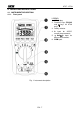
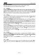
HT37 - HT39 4. OPERATING INSTRUCTIONS 4.1. INSTRUMENT DESCRIPTION 4.1.1. Front panel LEGEND: 1. LCD display. 2. Functions keys (RS-232 and keys for HT39 only). 3. Rotary selector. 4. A input for AC/DC current measurements. 5. HzVΩµA input for other measurements. 6. COM input. Fig.
HT37 - HT39 4.2. FUNCTION KEYS When pressing a key, the corresponding symbol is displayed with a beep. To resume default state turn the selector on another function. 4.2.1. MIN MAX By pressing MIN MAX key, maximum and minimum values are measured. Both values are stored and can be recalled by pressing the same key. The symbol corresponding to the desired function is displayed: “MAX” for maximum value, “MIN” for minimum value. MIN MAX key is disabled when HOLD function is active.
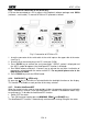
HT37 - HT39 4.2.5. RS-232 for connection to PC (HT39 only) HT39 can be connected to a PC by means of the optional software package mod. SW39 (software + serial cable). To connect HT39 to a PC proceed as follows: Fig. 2: Connection of HT39 to a PC 1. Insert the connector of the serial cable in the serial input on the upper side of the meter (see Fig. 2). 2. Insert the 9 pin connector plug in the PC serial port (COM). 3. Press RS-232 key to activate the serial connection.
HT37 - HT39 4.3. MEASUREMENTS 4.3.1. DC Voltage measurement CAUTION Maximum input for DC voltage is 1000V. Do not attempt to take any voltage measurement that exceeds the limits. Exceeding the limits could cause electrical shock and damage the multimeter. Fig. 3: DC Voltage measurement 1. Turn the selector on V. 2. Insert the test leads into the jacks, the red plug into HzVΩµA jack and the black plug into COM jack (Fig. 3). 3.
HT37 - HT39 4.3.2. AC Voltage measurement CAUTION Maximum input for AC voltage is 750V rms. Do not attempt to take any voltage measurement exceeding such limit to avoid the risk of electrical shock and damages to the instrument. Fig. 4: AC Voltage measurement 1. Turn the selector on ∼V. 2. Insert the test leads into the jacks, the red plug into HzVΩµA jack and the black plug into COM jack (Fig. 4). 3.
HT37 - HT39 4.3.3. DC Current measurement CAUTION Maximum input for DC current is 10A. Do not attempt to take any current measurement exceeding such limit to avoid the risk of electrical shock and damages to the instrument. Fig. 5: DC Current measurement 1. 2. 3. 4. 5. 6. 7. 8. 9. Switch OFF the circuit under test. Turn the selector on A. Insert the red test lead into A jack and the black plug into COM jack (Fig. 5).
HT37 - HT39 4.3.4. AC Current Measurement CAUTION Maximum input for AC current is 10A. Do not attempt to take any current measurement exceeding such limit to avoid the risk of electrical shock and damages to the instrument. Fig. 6: AC Current measurement 1. Switch OFF the circuit under test. 2. Turn the selector on ∼A. 3. Insert the test leads into the jacks, the red plug into A jack and the black plug into COM jack (Fig. 6). 4.
HT37 - HT39 4.3.5. Frequency measurement CAUTION Maximum input for AC voltage is 750V rms. Do not attempt to take any voltage measurement exceeding such limit to avoid the risk of electrical shock and damages to the instrument. Fig. 7: Frequency measurement 1. Turn the selector on Hz. 2. Insert the test leads into the jacks, the red plug into HzVΩµA jack and the black plug into COM jack (Fig. 7). 3.
HT37 - HT39 4.3.6. Resistance measurement CAUTION Before taking resistance measurements in circuit remove power from the circuit being tested and discharge all capacitors. Fig. 8: Resistance measurement 1. Turn the selector on Ω. 2. Insert the test leads into the jacks, the red plug into HzVΩµA jack and the black plug into COM jack (Fig. 8). 3. Connect the red and black test leads to the circuit under test, the resistance value will be displayed with automatic detection of the range. 4.
HT37 - HT39 4.3.7. Diode test and continuity test CAUTION Before taking resistance measurements in circuit remove power from the circuit being tested and discharge all capacitors. Fig. 9: Diode test and test continuity 1. Turn the selector on / . 2. Insert the test leads into the jacks, the red plug into HzVΩµA jack and the black plug into COM jack (Fig. 9). 3. Connect the red lead to the positive side (anode) of the diode and the black lead to the negative side (cathode).
HT37 - HT39 4.3.8. Capacitance measurement CAUTION Before taking any in circuit or capacitance measurement, remove power from the circuit being tested and discharge all capacitors. Use the short test lead pair for measurement in order to reduce the stray capacitance. Before connecting the test capacitor, note the display, which may show a reading other than zero whenever the range is changed. Subtract this offset reading from the test result of a capacitor to obtain the true value.
HT37 - HT39 5. MAINTENANCE 5.1. GENERAL INFORMATION 1. This is a precision instrument. To guarantee its performances be sure to use it according to these instructions and keep it stored on suitable environmental conditions. 2. Do not expose it to high temperatures or humidity or direct sunlight. 3. Be sure to turn it off after use. If you expect not to use the instrument for a long period remove batteries to avoid leakages of battery liquid which could damage the its inner components. 5.2.
HT37 - HT39 5.3. FUSE REPLACEMENT CAUTION Before replacing fuses, disconnect test leads from any energized circuit to avoid electrical shock. LEGEND: 1. Turn OFF the meter and disconnect the test leads from the input terminals. 2. Remove the protective holster from the meter. 3. Unscrew the battery cover and remove the battery. 4. Remove the defective fuse and install a new fuse of the same size and rating (fast type 10A/1000V). Make sure the new fuse is centered in the fuse holder.
HT37 - HT39 6. TECHNICAL SPECIFICATIONS 6.1. TECHNICAL FEATURES The accuracy is indicated as [% of reading + number of digits]. It is referred to the following environmental conditions: temperature 23°C ± 5°C, relative humidity < 80%. DC Voltage Range 400.0mV 4.000V 40.00V 400.0V 1000V Resolution 0.1mV 0.001V 0.01V 0.1V 1V Accuracy Input impedance Overload protection ±(0.
HT37 - HT39 Resistance Range 400.0Ω 4.000kΩ 40.00kΩ 400.0kΩ 4.000MΩ 40.00MΩ Resolution 0.1Ω 0.001kΩ 0.01kΩ 0.1kΩ 0.001MΩ 0.01MΩ Accuracy ±(1.0%rdg+5dgt) Open voltage Overload protection 1.3V 600V rms ±(0.7%rdg+2dgt) ±(1.0%rdg+2dgt) ±(1.5%rdg+5dgt) Diode test Range Resolution Accuracy (0.4 ÷ 0.8V) Test current Open voltage Overload protection 10mV ±(1.5%rdg+5dgt) 1.5mA <3V 600V rms Continuity test Range Buzzer Overload protection R<450Ω 600V rms Accuracy ±(3.
HT37 - HT39 6.1.3. General data Mechanical characteristics Dimensions (with holster): Weight (including battery): Power supply Battery type: Low battery indication: Battery life: AutoPowerOFF: Display Specifications: 164x82x44mm About 400g 9V NEDA1604, JIS006P, IEC6F22 " " is displayed when battery voltage is too low About 300 hours 30 minutes after last pressure on keys or rotation of selector Over range indication: 4 LCD with max.
HT37 - HT39 7. SERVICE 7.1. WARRANTY CONDITIONS This instrument is guaranteed for one year against material or production defects, in accordance with our general sales conditions. During the warranty period the manufacturer reserves the right to decide either to repair or replace the product. Should you need for any reason to return back the instrument for repair or replacement take prior agreements with the local distributor from whom you bought it.