ENGLISH User manual Copyright HT ITALIA 2012 Release EN 2.
HT327 Table of Contents: 1. SAFETY PRECAUTIONS AND PROCEDURES .......................................................... 2 1.1. 1.2. 1.3. 1.4. 2. GENERAL DESCRIPTION ........................................................................................... 4 2.1. 2.2. 3. Mean value and TRMS: definition ..................................................................................... 4 True root mean square value and crest factor: definition ..................................................
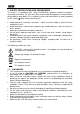
HT327 1. SAFETY PRECAUTIONS AND PROCEDURES This meter is in compliance with safety IEC/EN61010-1 guideline related to electronic measuring instruments. For your own safety and to avoid damaging the instrument follow the procedures described in this instruction manual and read carefully all notes preceded by this symbol .When taking measurements: Avoid doing that in humid or wet places - make sure that humidity is within the limits indicated in § 6.2.1.
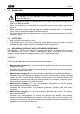
HT327 1.2. DURING USE CAUTION An improper use may damage the instrument and/or its components or injure the operator. When changing the range, first disconnect the test leads from the circuit under test in order to avoid any accident. When the instrument is connected to measuring circuits never touch any unused terminal. When measuring resistors do not add any voltage. Although there is a protection circuit, excessive voltage could cause malfunctioning.
HT327 2. GENERAL DESCRIPTION This meter performs the below listed measurements: DC and AC TRMS Voltage DC and AC TRMS Current Resistance and Continuity test Frequency Capacitance Diode test All selectable by means of a 10 position rotary selector (including OFF position). Functions keys are also available (see § 4.2). An analogical bargraph is also available. The selected quantity is displayed with indication of measuring unit and active functions.
HT327 3. PREPARATION FOR USE 3.1. INITIAL This instrument was checked both mechanically and electrically prior to shipment. All possible cares and precautions were taken to let you receive the instrument in perfect conditions. Notwithstanding we suggest you to check it rapidly (eventual damages may have occurred during transport. If so contact the local distributor from whom you bought the item). Make sure that all standard accessories mentioned in § 6.3.1 are included.
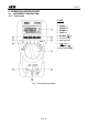
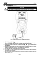
HT327 4. OPERATING INSTRUCTIONS 4.1. INSTRUMENT - DESCRIPTION 4.1.1. Front panel LEGEND: 1. LCD 2. HOLD Key 3. PK/ REL Key 4. MX/ MN Key 5. R/SEL Key 6. 7. 8. 9. Backlight Key Function selector Input terminal A Input terminal V Hz A 10. Input terminal COM Fig.
HT327 4.2. DESCRIPTION OF FUNCTION KEYS 4.2.1. HOLD key By pressing HOLD key the measured value is frozen on the display where the symbol "HOLD" appears. Press again HOLD to disable this function and resume normal operation. 4.2.2. PK/REL key This key have the double function of measuring max/min peak values (active for V and A positions of rotary selector) and performing relative measurements (REL) for V, A, Hz, / , , and A positions of rotary selector.
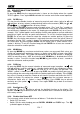
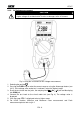
HT327 4.3. MEASUREMENTS 4.3.1. DC Voltage measurement CAUTION The maximum input for DC voltage is 1000V. Do not attempt to measure higher voltages to avoid electrical shocks or damages to the instrument. Fig. 2: Using the meter for DC Voltage measurement 1. Selecting the position V . 2. Pressing the R/SEL key to select the correct range or using the Autorange feature (see § 4.2). If the voltage value under test is unknown, select the highest range. 3.
HT327 4.3.2. AC Voltage measurement CAUTION The maximum input for AC voltage is 750Vrms. Do not attempt to measure higher voltages to avoid electrical shocks or damages to the instrument. Fig. 3: Using the instrument for AC Voltage measurement 1. Selecting the position 2. Pressing the R/SEL key to select the correct range or using the Autorange feature (see § 4.2). If the voltage value under test is unknown, select the highest range 3.
HT327 4.3.3. DC Current measurement CAUTION The maximum input for DC current is 10A. Do not attempt to measure higher currents to avoid electrical shocks or damages to the instrument. Fig. 4: Using the instrument for DC Current measurement 1. Power off the circuit under test. 2. Selecting the position . The message “ ” is shown at display. 3. Insert the test leads into the jacks, the red plug into A jack and black plug into COM jack 4.
HT327 4.3.4. AC Current measurement CAUTION The maximum input for DC current is 10A. Do not attempt to measure higher currents to avoid electrical shocks or damages to the instrument. Fig. 5: Using the instrument for AC Current measurement 1. Power off the circuit under test 2. Selecting the position . By pressing R/SEL key to select AC measurement. The “ ” symbol is shown at display 3. Insert the test leads into the jacks, the red plug into A jack and black plug into COM jack 4.
HT327 4.3.5. Resistance measurement and Continuity Test CAUTION Before taking resistance measurements on the circuit remove power from the circuit being tested and discharge all capacitors. Fig. 6: Using the instrument for Resistance measurement and Continuity test 1. Selecting the position / 2. Insert the test leads into the jack, the red plug into V Hz A jack and black plug into COM jack 3. Connect the test leads to the circuit under test (see Fig. 6). The resistance value is displayed 4.
HT327 4.3.6. Diode test CAUTION Before taking diode test on remove power from the circuit being tested and discharge all capacitors. Fig. 7: Using the instrument for Diode test 1. Selecting the position 2. Insert the test leads into the jacks, the red plug into V Hz A jack, and black plug into COM jack 3. Connect the test leads to the diode under test observing the proper polarities (see Fig. 7). The threshold voltage value of direct polarization is shown at display.
HT327 4.3.7. Capacitance measurement CAUTION Before taking capacitance measurements in circuit remove power from the circuit being tested and discharge all capacitors. Due to internal delay time, bargraph it’s no operative in capacitance measurement. Fig. 8: Using the instrument for Capacitance measurement 1. 2. 3. 4. 5. 6.
HT327 4.3.8. Frequency measurement CAUTION The maximum input for AC voltage is 750Vrms. Do not attempt to measure higher voltages to avoid electrical shocks or damages to the instrument. Fig. 9: Using the instrument for Frequency measurement 1. Selecting the position Hz. Hz A jack and black plug 2. Insert the test leads into the jacks, the red plug into V into COM jack 3. Connect the test leads to the circuit under test (see Fig. 9). The frequency value will be displayed. 4.
HT327 5. MAINTENANCE CAUTION Only skilled technicians can open the instrument and replace batteries. Before removing batteries disconnect the test leads from the input terminals to avoid electrical shocks Do not expose it to high temperatures or humidity or direct sunlight Be sure to turn it off after use. If you expect not to use the instrument for a long period remove batteries to avoid leakages of battery liquid which could damage its inner components 5.1.
HT327 6. TECHNICAL SPECIFICATIONS 6.1. TECHNICAL FEATURES Accuracy is indicated as [%reading + (number of digits*resolution)] at 23°C±5°C, < 80%HR DC Voltage Range Resolution Accuracy 400.0mV 4.000V 40.00V 400.0V 1000V 0.1mV 0.001V 0.01V 0.1V 1V (0.5%rdg + 3dgt) (0.5%rdg + 2dgt) Input impedance Overload protection 10M // <100pF 1000VDC 750VACrms Input impedance Overload protection 10M // <100pF 1000VDC 750VACrms (1.0%rdg + 2dgt) AC TRMS Voltage Range Resolution 400.0mV 0.1mV 4.
HT327 Diode Test Feature Resolution 10mV Accuracy (0.4 0.8V) (1.5%rdg + 5dgt) Test current Open voltage Overload protection 1.5mA <3V 600Vrms Continuity Test Feature Buzzer Open voltage <35 about 1.3V Overload protection 600Vrms Frequency Range 4.000kHz Resolution 0.001kHz 40.00kHz 0.01kHz Accuracy (0.1%rdg + 2dgt) Sensitivity Overload protection 1.5V ÷ 600VACrms (0 ÷ 1.000kHz) 600Vrms 2.0V ÷ 5VACrms (1.000kHz ÷ 40.
HT327 6.1.1. Electrical specifications Conversion: Measuring rate: Temperature coefficient: NMRR Normal Mode Rejection Ratio: CMRR Common Mode Rejection Ratio: TRMS 1.5 times per second 0.15×(accuracy)/°C (<18°C and >28°C) >50dB for DC parameters and 50/60Hz >100dB from DC up to 60Hz on DCV >60dB from DC up to 60Hz on ACV 6.1.2.
HT327 7. SERVICE 7.1. WARRANTY CONDITIONS This instrument is guaranteed against material or production defects, in accordance with our general sales conditions. During the warranty period the manufacturer reserves the right to decide either to repair or replace the product. Should you need for any reason to return back the instrument for repair or replacement take prior agreements with the local distributor from whom you bought it.