ENGLISH User manual Copyright HT ITALIA 2012 Release EN 2.
HT326 Table of Contents: 1. SAFETY PRECAUTIONS AND PROCEDURES .......................................................... 2 1.1. Preliminary ........................................................................................................................ 2 1.2. During use ......................................................................................................................... 3 1.3. After use ..............................................................................................
HT326 1. SAFETY PRECAUTIONS AND PROCEDURES This meter is in compliance with IEC/EN61010-1 guideline related to electronic measuring instruments. For your own safety and to avoid damaging the instrument follow the procedures described in this instruction manual and read carefully all notes preceded by this symbol .When taking measurements: Avoid doing that in humid or wet places Avoid doing that in rooms where explosive gas, combustible gas, steam or excessive dust is present.
HT326 1.2. DURING USE Read the recommendations which follow and the instructions in this manual: CAUTION An improper use may damage the instrument and/or its components or injure the operator. When changing the range, first disconnect the test leads from the circuit under test in order to avoid any accident. When the instrument is connected to measuring circuits never touch any unused terminal. When measuring resistors do not add any voltage.
HT326 2. GENERAL DESCRIPTION This meter performs the below listed measurements: DC Voltage AC sine wave Voltage DC Current AC sine wave Current Resistance Continuity Diode test Frequency Duty cycle Capacitance All selectable by means of a 10 addition there are the HOLD key selection of measuring ranges, the selection between Frequency and measurements. position rotary selector (including OFF position).
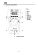
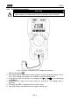
HT326 4. OPERATING INSTRUCTIONS 4.1. INSTRUMENT - DESCRIPTION 4.1.1. Front panel CAPTION: 1. LCD display 2. HOLD Key 3. R Key 4. REL Key 5. SEL Key 6. Backlight Key 7. Function selector 8. Input terminal A 9. Input terminal VHz 10. Input terminal COM Fig.
HT326 4.2. DESCRIPTION OF FUNCTION KEYS 4.2.1. HOLD key By pressing HOLD key the measured value is frozen on the display where the symbol "HOLD" appears. Press again HOLD to disable this function and resume normal operation. 4.2.2. R (RANGE) key By pressing R key, the manual mode is activated and the “AUTO” symbol disappears from the display. Press R cyclically to change the measuring range and fix the decimal point on the display.
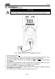
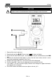
HT326 4.3. MEASUREMENTS 4.3.1. DC Voltage measurement CAUTION The maximum input for DC voltage is 600V. Do not attempt to measure higher voltages to avoid electrical shocks or damages to the instrument. Fig. 2: Using the meter for DC Voltage measurement 1. Selecting the position V . 2. Pressing the R key to select the correct range or using the Autorange feature (see § 4.2.2). If the voltage value under test is unknown, select the highest range. 3.
HT326 4.3.2. AC Voltage measurement CAUTION The maximum input for AC voltage is 600V. Do not attempt to measure higher voltages to avoid electrical shocks or damages to the instrument. Fig. 3: Using the instrument for AC Voltage measurement 1. Selecting the position 2. Pressing the R key to select the correct range or using the Autorange feature (see § 4.2.2). If the voltage value under test is unknown, select the highest range. 3.
HT326 4.3.3. DC Current measurement CAUTION The maximum input for DC current is 10A. Do not attempt to measure higher currents to avoid electrical shocks or damages to the instrument. Fig. 4: Using the instrument for DC Current measurement 1. Power off the circuit under test 2. Selecting the position . The message “ ” is shown at display 3. Insert the test leads into the jacks, the red plug into A jack and black plug into COM jack 4.
HT326 4.3.4. AC Current measurement CAUTION The maximum input for DC current is 10A. Do not attempt to measure higher currents to avoid electrical shocks or damages to the instrument. Fig. 5: Using the instrument for AC Current measurement 1. Power off the circuit under test. 2. Selecting the position ” symbol is shown at display 3. Press the SEL key to select AC measurement. The “ 4. Insert the test leads into the jacks, the red plug into A jack and black plug into COM jack 5.
HT326 4.3.5. Resistance measurement CAUTION Before taking resistance measurements on the circuit remove power from the circuit being tested and discharge all capacitors. Fig. 6: Using the instrument for Resistance measurement 1. Selecting the position 2. Pressing the R key to select the correct range or using the Autorange feature (see § 4.2.2). If the resistance value under test is unknown, select the highest range. 3.
HT326 4.3.6. Continuity test CAUTION Before taking resistance measurements on the circuit remove power from the circuit being tested and discharge all capacitors. Fig. 7: Using the instrument for Continuity test 1. Selecting the position jack and black plug 2. Insert the test leads into the jacks, the red plug into VHz into COM jack 3. Connect the test leads to the circuit under test (see Fig. 7) 4.
HT326 4.3.7. Diode test CAUTION Before taking resistance measurements on the circuit remove power from the circuit being tested and discharge all capacitors. Fig. 8: Using the instrument for Diode test 1. Selecting the position 2. Insert the test leads into the jacks, the red plug into VHz jack, and black plug into COM jack 3. Connect the test leads to the diode under test observing the proper polarities (see Fig. 8) 4. The threshold voltage value of direct polarization is shown at display 5.
HT326 4.3.8. Frequency and Duty Cycle measurement CAUTION The maximum input for AC voltage is 600V. Do not attempt to measure higher voltages to avoid electrical shocks or damages to the instrument. Fig. 9: Using the instrument for frequency measurement 1. Selecting the position Hz/Duty. The symbol “Hz” is shown at display 2. Insert the test leads into the jacks, the red plug into VHz jack and black plug into COM jack 3. Connect the test leads to the circuit under test (see Fig. 9).
HT326 4.3.9. Capacitance measurement CAUTION Before taking capacitance measurements in circuit remove power from the circuit being tested and discharge all capacitors. Connect the test capacitor to the inputs respecting the polarity connections when required. Fig. 10: Using the instrument for Capacitance measurement 1. 2. 3. 4. 5.
HT326 5. MAINTENANCE CAUTION Only skilled technicians can open the instrument and replace batteries. Before removing batteries disconnect the test leads from the input terminals to avoid electrical shocks Do not expose it to high temperatures or humidity or direct sunlight Be sure to turn it off after use. If you expect not to use the instrument for a long period remove batteries to avoid leakages of battery liquid which could damage its inner components 5.1.
HT326 6. TECHNICAL SPECIFICATIONS 6.1. TECHNICAL FEATURES Accuracy is indicated as [%reading + (number of digits*resolution)] at 23°C±5°C, < 75%HR DC Voltage Range Resolution Accuracy 400mV 4V 40V 400V 600V 0.1mV 0.001V 0.01V 0.1V 1V (0.8%rdg + 3dgt) (0.8%rdg + 2dgt) Input impedance Overload protection 10M 600V DC/AC rms Input impedance Overload protection 10M 600V DC/ACrms (1.0%rdg + 2dgt) AC Voltage Accuracy (40400Hz) not declared Range Resolution 400mV 4V 40V 400V 600V 0.1mV 0.
HT326 Diode Test Feature Direct voltage Accuracy Max Open Circuit Voltage 0 – 1.000V (0.5%rdg + 3dgt) 1.5V Overload protection 600V DC/AC rms <30sec Continuity test Feature Buzzer Test current Max Open Circuit Voltage <140 about 1mA about 0.5V Overload protection 600V DC/AC rms <30sec Frequency (Autorange) Range 99.99Hz 999.9Hz 9.999kHz 99.99kHz Resolution 0.01Hz 0.1Hz 1Hz 10Hz Accuracy Overload protection (1.
HT326 6.1.1. Reference standards Safety: Insulation: Pollution degree: Overvoltage category: Max height of use: IEC/EN61010-1 double insulation 2 CAT III 1000V, CAT IV 600V 2000m; 6561ft 6.1.2. General data Mechanical characteristics Dimensions (L x W x H): Weight (including batteries): 163 x 88 x 48mm; 6.4 x 3.5 x 1.9in 280g; 9.9 ounces Power supply Battery type: Indication of low batteries: Battery life: Fuse: 2x1.5V batteries type AAA MN2400 LR03 AM4 symbol " " is displayed Approx.
HT326 7. SERVICE 7.1. WARRANTY CONDITIONS This instrument is guaranteed against material or production defects, in accordance with our general sales conditions. During the warranty period the manufacturer reserves the right to decide either to repair or replace the product. Should you need for any reason to return back the instrument for repair or replacement take prior agreements with the local distributor from whom you bought it.