ENGLISH User manual Copyright HT ITALIA 2012 Release EN .
GEO416 - GEO416GS Table of contents: 1. SAFETY PRECAUTIONS AND PROCEDURES .......................................................... 2 1.1. 1.2. 1.3. 1.4. 2. GENERAL DESCRIPTION ........................................................................................... 4 2.1. 3. Instrument description ....................................................................................................... 4 PREPARING THE INSTRUMENT .........................................................................
GEO416 - GEO416GS 1. SAFETY PRECAUTIONS AND PROCEDURES The instrument was designed in compliance with standards IEC/EN61557 and IEC/EN61010-1 relative to electronic equipment.
GEO416 - GEO416GS 1.2. DURING USE You are recommended to read carefully the following instructions: CAUTION Failure to comply with warnings and instructions may damage the instrument and/or its components as well as injure the operator. If the low battery symbol is displayed during use interrupt testing and replace batteries following the procedure described in § 8.
GEO416 - GEO416GS 2. GENERAL DESCRIPTION This instrument will grant you accurate and reliable measurements provided that is used according to the instructions given in this manual. You will enjoy the highest safety thanks to a development of newest conception assuring double insulation and over voltage category III. 2.1. INSTRUMENT DESCRIPTION EARTH 2W: 2-wire earth resistance measurement EARTH 3W: 3-wire earth resistance measurement ρ: 4-wire ground resistivity measurement. 3.
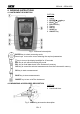
GEO416 - GEO416GS 4. WORKING INSTRUCTIONS 4.1. INSTRUMENT DESCRIPTION CAPTION: 1. 2. 3. 4. 5. 6. 7. 8. Inputs ENTER/,,,keys ESC/ key RCL/CLR key Display GO key SAVE key ON/OFF key Fig.
GEO416 - GEO416GS 4.2.1. Switching on When switching on the instrument a brief tone is audible along with display of all segments for about one second. Subsequently the last firmware version as well as the last selected measuring mode are displayed before switching off. 4.2.2. Auto power off The instrument automatically turns off 3 minutes after the last key pressing. To resume operation turn on the instrument pressing the on/off key.
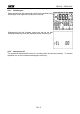
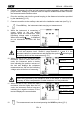
GEO416 - GEO416GS 4.3. EARTH 3W – 3 WIRE EARTH RESISTANCE MEASUREMENT The measurement is carried out in compliance with standards IEC 781, VDE 0413, IEC/EN61557-5. CAUTION The instrument can be used for voltage and current measurements on installations with over voltage category CAT III 240V to earth and maximum voltage of 415V between inputs. Do not connect the instrument to installations whose voltages exceed the limits indicated in this manual.
GEO416 - GEO416GS 5. Extend, if necessary, the blue and red measuring cables separately using cables with proper section. Adding any extension does not require calibration and does not affect the measured earth resistance value 6. Drive the auxiliary rods into the ground keeping to the distance instructions provided by the standards (§ 11.2) 7. Connect crocodiles to the auxiliary rods and to the installation under test (see Fig. 3) 8. 9.
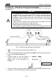
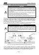
GEO416 - GEO416GS 4.4. EARTH 2W – 2 WIRE EARTH RESISTANCE MEASUREMENT CAUTION The instrument can be used for voltage and current measurements on installations with over voltage category equal to CAT III 240V to earth and maximum voltage of 415V between inputs. Do not connect the instrument to installations whose voltages exceed the limits indicated in this manual.
GEO416 - GEO416GS CAUTION If you wish to effect the measurement using the neutral and earth conductors of an ordinary socket, you may accidentally connect to phase; in this case the detected voltage as well as the warning symbol for wrong entering will be displayed and no measurement will be effected even though the GO key is pressed Fig. 5: Two-wire earth resistance measurement from the panel board 1. Turn the instrument on pressing the ON/OFF key 2.
GEO416 - GEO416GS 8. While the instrument is measuring a screen similar to the one beside appears where the instrument’s input interfering voltage value is displayed. When the message is displayed do not disconnect or touch the test leads Input interfering value voltage CAUTION When starting measurement the input interfering voltage is measured at both the volt and ampere circuit.
GEO416 - GEO416GS 4.5. - GROUND RESISTIVITY MEASUREMENT The ground resistivity value is an essential parameter to calculate the resistance value of the earth rods to be used for the earth installation’s construction. The measurement is effected according to standards IEC 781, VDE 0413, IEC/EN61557-5. CAUTION The instrument can be used for voltage and current measurements on installations with over voltage category equal to CAT III 240V to earth and maximum voltage of 415V between inputs.
GEO416 - GEO416GS 3. 4. 5.
GEO416 - GEO416GS 11. While the instrument is measuring a screen similar to the one beside appears where the instrument’s input interfering voltage value and the distance set between auxiliary rods are displayed. When the message is displayed do not disconnect or touch the test leads Value of input interfering voltage and rods' distance set CAUTION When starting measurement the input interfering voltage is measured at both the volt and ampere circuit.
GEO416 - GEO416GS 4.5.1. Anomalous measuring applications 1. When starting a measurement the Volt circuit’s resistance too instrument checks the continuity of high measuring cables. If the volt circuit (red cable S and green cable ES) is interrupted or its resistance value is Value of input interfering voltage too high, the instrument displays a screen similar to the one beside.
GEO416 - GEO416GS 4. When starting a measurement, if the red cable (connected to S terminal) and the green cable (connected to ES terminal) are reversed, the instrument do not perform the test, emits a long sound tone and displays the screen beside Red and reversed green cables Example under ρ mode 5.
GEO416 - GEO416GS 5. MANAGEMENT OF STORED DATA 5.1. HOW TO SAVE A MEASUREMENT After taking a measurement press SAVE key, the instrument displays a screen similar to the one beside 1. Last value set parameters L and P for Should you need to modify the values of the parameters L and P press the arrow keys , and select L or P, then pressing the arrow keys , set the desired value (from 1 to 255). These values can enable you to trace back the place where the measurement was effected 2. 3. No.
GEO416 - GEO416GS Press the CLR key, the instrument displays a screen similar to the one beside 3. First and last memory location to be cancelled and confirmation required Alternatively: 4. Confirm cancellation of measurements pressing ENTER key, the instrument emits a double sound tone confirming cancellation of the selected measurements 4. Press ESC key to go back to previous screen Or: 5.3. HOW TO RECALL A MEASUREMENT 1.
GEO416 - GEO416GS 6. INSTRUMENT RESET CAUTION BEFORE CARRYING OUT THE INSTRUMENT’S RESET SAVE ALL DATA RELATIVE TO THE MEASUREMENTS EFFECTED BY DOWNLOADING THEM TO A PC 1. When the instrument is off press the RCL/CLR key 2. Keeping down the RCL/CLR key, press the switch on key. The instrument emits a short sound tone showing all display segments for approx. 1 second. Then it emits a second short sound tone displaying the screen beside for approx.
GEO416 - GEO416GS 8. MAINTENANCE 8.1. GENERAL This is a precision instrument. Strictly follow the instructions for use and storage reported in this manual to avoid any possible damage or danger during use. Do not use this tester under unfavorable conditions of high temperature or humidity. Do not expose to direct sunlight. Be sure to turn off the tester after use.
GEO416 - GEO416GS 9. TECHNICAL SPECIFICATIONS 9.1. TECHNICAL FEATURES Accuracy indicated as [%reading + (number dgts * resolution)] at 23 ± 5°C, <80%RH 3- and 2-wire earth resistance measurement - EARTH 3W and EARTH 2W Measurement range (**) Accuracy (*) Resolution [] Reading [] Measure [] 0.01 0.01 19.99 0.08 19.99 0.1 20.0 199.9 20.0 199.9 1 (2.5%rdg + 2dgt) 200 1999 200 1999 0.01k 2.00 19.99k 2.00 19.99k 0.1k 20.0 49.9k 20.0 49.
GEO416 - GEO416GS 9.1.1. Reference standards Safety: Measuring accessories’ safety: Technical literature: Insulation: Mechanical protection: Pollution level: Measurement category: Max height of use: IEC/EN61010-1, IEC/EN61557-1, IEC/EN61557-5 IEC/EN61010-031 IEC/EN61187 double insulation IP50 according IEC/EN60529 2 CAT III 240V (to earth), maximum 415V between inputs 2000m (6562ft) 9.1.2.
GEO416 - GEO416GS 10. SERVICE 10.1. WARRANTY TERMS This instrument is guaranteed against material or manufacturing defects, in accordance with general sales conditions. During the warranty period the manufacturer reserves the right to decide either to repair or replace the product. Should you need for any reason to return back the instrument for repair or replacement take prior agreements with your local distributor. Freight charges are up to the customer.
GEO416 - GEO416GS 11. PRACTICAL REPORTS FOR ELECTRICAL TESTS 11.1. EARTH RESISTANCE IN TT SYSTEMS The test is aimed at checking that the RCD is coordinated with the earth resistance value. It is not possible to assume an earth resistance value as reference limit when controlling the test result, while it is necessary to check every time that the co-ordination complies with the requirements of the Standards. The parts to be checked are represented by the whole earth installation under working conditions.
GEO416 - GEO416GS 11.2. EARTH RESISTANCE, VOLTAAMPEREMETRIC METHOD 11.2.1. Creating cables extensions If the length of the supplied cables isn’t suitable for the plant under test, You can create your own extensions without influencing the instrument’s accuracy.
GEO416 - GEO416GS Fig. 8: Earth resistance measurement – large-sized earth rods 11.3. GROUND RESISTIVITY This test aims at analyzing the resistivity value of the ground in order to define the type of rods to be used when designing the installation. For the resistivity test correct or not correct values do not exist. The various values measured by positioning the rods at growing distances “a” must be quoted in a graph. According to the resulting curve, suitable rods will be chosen.
GEO416 - GEO416GS The measuring method allows defining the specific resistivity of a ground layer up to the depth corresponding approximately to the distance “a” between the rods. If you increase the distance “a” you can reach deeper ground layers and check the ground homogeneity. After several measurements you can trace a profile according to which the most suitable rod is chosen.
ESPAÑOL Manual de instrucciones Copyright HT ITALIA 2012 Versión ES .
GEO416 - GEO416GS Índice: 1. PRECAUCIONES Y MEDIDAS DE SEGURIDAD ........................................................ 2 1.1. 1.2. 1.3. 1.4. 2. DESCRIPCIÓN GENERAL ........................................................................................... 4 2.1. 3. Funcionalidad del instrumento .......................................................................................... 4 PREPARACIÓN PARA EL USO ................................................................................... 4 3.1.
GEO416 - GEO416GS 1. PRECAUCIONES Y MEDIDAS DE SEGURIDAD El instrumento ha sido proyectado conforme a las directivas IEC/EN61557-1 y IEC/EN 61010-1 relativas a los instrumentos de medida electrónicos.
GEO416 - GEO416GS 1.2. DURANTE EL USO Le rogamos que lea atentamente las recomendaciones y las instrucciones siguientes: ATENCIÓN La falta de observación de las Advertencias y/o Instrucciones pueden dañar el instrumento y/o sus componentes o ser fuente de peligro para el usuario. Si durante el uso aparece el símbolo de pila agotada, suspenda la prueba y sustituya las pilas según el procedimiento descrito en el § 8.
GEO416 - GEO416GS 2. DESCRIPCIÓN GENERAL El instrumento está realizado de modo que garantiza la máxima seguridad gracias a un desarrollo de nueva concepción que asegura el doble aislamiento y el cumplimiento de la categoría de sobretensión III. 2.1. FUNCIONALIDAD DEL INSTRUMENTO EARTH 2P: medida de la resistencia de tierra a 2 puntos EARTH 3P: medida de la resistencia de tierra a 3 puntos ρ: medida de la resistividad del terreno a 4 puntos 3. PREPARACIÓN PARA EL USO 3.1.
GEO416 - GEO416GS 4. INSTRUCCIONES OPERATIVAS 4.1. DESCRIPCIÓN DEL INSTRUMENTO LEYENDA: 1. Entradas 2. Tecla ENTER/,,, 3. Tecla ESC/ 4. Tecla RCL/CLR 5. Visualizador 6. Tecla GO 7. Tecla SAVE 8. Tecla ON/OFF Fig.
GEO416 - GEO416GS 4.2.1. Encendido Al encender el instrumento emite una breve señal acústica y durante un segundo se visualizan todos los segmentos del visualizador. Sucesivamente muestra la versión del firmware cargada, luego aparece la última modalidad de medición seleccionada antes del apagado. 4.2.2. Autoapagado El instrumento se apaga después de aproximadamente 3 minutos desde el último uso de las teclas. Para reactivar el instrumento pulse cualquier tecla.
GEO416 - GEO416GS 4.3. EARTH 3W – MEDICIÓN DE LA RESISTENCIA DE TIERRA A 3 PUNTOS La medida será efectuada en acuerdo con la normativa UNE 20460, IEC 781, VDE 0413, IEC/EN61557-5 ATENCIÓN El instrumento puede ser utilizado sobre instalaciones con categoría de sobretensión CAT III 240V respecto tierra con tensiones máximas de 415V entre las entradas. No conecte el instrumento a una instalación con tensiones que excedan los límites indicados en este manual.
GEO416 - GEO416GS 5. 6. 7. 8. 9. Prolongue, si fuese necesario, los cables de medida azul y rojo separadamente utilizando cables de sección adecuada. La presencia de eventuales prolongaciones no requiere calibración y no modifica el valor de la resistencia de tierra medida Clave en el terreno los dispersores auxiliares según la distancia prevista por la norma (§ 11.2) Coloque los cocodrilos a los dispersores auxiliares a la instalación en examen (ver Fig.
GEO416 - GEO416GS 4.4. EARTH 2W – MEDICIÓN DE LA RESISTENCIA DE TIERRA A 2 PUNTOS ATENCIÓN El instrumento puede ser utilizado sobre instalaciones con categoría de sobretensión CAT III 240V respecto tierra con tensiones máximas de 415V entre las entradas. No conecte el instrumento a una instalación con tensiones que excedan los límites indicados en este manual.
GEO416 - GEO416GS ATENCIÓN Si se desea efectuar la medida utilizando el conductor de neutro y de tierra de una toma de corriente, evite conectar accidentalmente sobre la fase; en cuyo caso el visualizador indicará la tensión detectada, aparecerá el símbolo de con la señal de advertencia y no podrá efectuar la medida ATENCIÓN aunque pulse la tecla GO Fig. 5: Medición de la resistencia de tierra a dos puntos desde el cuadro de alimentación 1. Encienda el instrumento pulsando el botón ON/OFF 2.
GEO416 - GEO416GS 8. Mientras el instrumento efectua la medición será visualizada una ventana como la muestra donde será mostrado el valor de la tensión de dispersión en la entrada del instrumento. Mientras sobre el visualizador del instrumento aparece el mensaje no desconecte y no toque las puntas de prueba Valor de la tensión de dispersión en la entrada ATENCIÓN Al inicio de la medición será medida la tensión de dispersión en las entradas del circuito voltimétrico y amperimétrico.
GEO416 - GEO416GS 4.5. - MEDICIÓN DE LA RESISTIVIDAD DEL TERRENO El valor de la resistividad del terreno es un parámetro indispensable para calcular el valor de la resistencia de los dispersores que se van a utilizar para la realización de una instalación de tierra. La medida será efectuada en acuerdo con las normativas UNE 20460, IEC 781, VDE 0413, IEC/EN61557-5.
GEO416 - GEO416GS 3. 4. 5.
GEO416 - GEO416GS 11. Mientras el instrumento efectua la medición será visualizada una ventana como la muestra donde será mostrado el valor de la tensión de dispersión en la entrada del instrumento.
GEO416 - GEO416GS 4.5.1. Situaciones anómalas en mediciones 1. Al inicio de la medición el instrumento Resistencia del circuito verifica la continuidad de los cables de voltimétrico muy elevada medida. Cuando el circuito voltimétrico (cable rojo S y verde ES) esté interrumpido o presente una Valor de la tensión de resistencia muy elevada, el dispersión en las entradas instrumento visualiza la siguiente pantalla.
GEO416 - GEO416GS 4. Al inicio de la medición, cuando los cables rojo (conectado al terminal S) y verde (conectado al terminal ES) estén invertidos entre ellos, el instrumento no efectua la prueba, emite un señal acústica prolongada y visualizará la siguiente pantalla Cable rojo y verde invertidos entre ellos Ejemplo en modalidad ρ 5.
GEO416 - GEO416GS 5. GESTIÓN DE LOS DATOS EN MEMORIA 5.1. 1. COMO GUARDAR UNA MEDIDA Después de haber efectuado una medición pulse la tecla SAVE, el instrumento visualiza la siguiente pantalla Número de la localización de memoria en la cual será memorizada la medida Útimo valor guardado del parámetro L y del parámetro P 2. 3. 5.2. 1.
GEO416 - GEO416GS Pulse la tecla CLR, instrumento visualiza siguiente pantalla 3. el la Primera y última localización de memoria cancelada y confirmada En alternativa: 4. Confirmar la cancelación de las medidas pulsando la tecla ENTER, el instrumento emite una doble señal acústica indicando la cancelación de las medidas seleccionadas O bien: 4. 5.3. 1.
GEO416 - GEO416GS 6. RESET DEL INSTRUMENTO ATENCIÓN ANTES DE EJECUTAR EL RESET AL INSTRUMENTO GUARDE LOS DATOS RELATIVOS A LAS MEDIDAS EFECTUADAS TRANSFIRIENDOLAS A UN PC 1. Antes de encender el instrumento pulse la tecla RCL/CLR 2. Mantenga pulsada la tecla RCL/CLR, pulse la tecla de encendido. El instrumento emite un breve señal acústica y durante un segundo muestra todos los segmentos del visualizador.
GEO416 - GEO416GS 8. MANTENIMIENTO 8.1. GENERALIDADES El instrumento que Usted ha adquirido es un instrumento de precisión. Durante el uso y el almacenamiento respete las recomendaciones enumeradas en este manual para evitar posibles daños o peligros durante el uso. No utilice el instrumento en entornos caracterizados por elevadas tasas de humedad o temperatura. No lo exponga directamente a la luz del sol. Apague siempre el instrumento después del uso.
GEO416 - GEO416GS 9. ESPECIFICACIONES TÉCNICAS 9.1. CARACTERÍSTICAS TÉCNICAS Incertidumbre indicada es [%lectura + (número digs*resolución)] a 23°C±5°C, < 80%HR Mediciones de la resistencia de tierra a 3 y a 2 puntos - EARTH 3W y EARTH 2W Escala (**) Incertidumbre (*) Resolución [] Lectura [] Medida [] 0.01 0.01 19.99 0.08 19.99 0.1 20.0 199.9 20.0 199.9 1 (2.5%lectura + 2cifras) 200 1999 200 1999 0.01k 2.00 19.99k 2.00 19.99k 0.1k 20.0 49.9k 20.0 49.
GEO416 - GEO416GS 9.1.1. Normas de referencia Seguridad: Seguridad accesorios de medida: Documentación técnica: Aislamiento: Protección: Nivel de polución: Categoría de sobretensión: Altitud máx de uso: IEC/EN61010-1, IEC/EN61557-1, IEC/EN61557-5 IEC/EN61010-031, IEC/EN61010-2-032 IEC/EN61187 doble aislamiento IP50 según IEC / EN60529 2 CAT III 240V (respecto tierra), max 415V entre entradas 2000m 9.1.2.
GEO416 - GEO416GS 10. ASISTENCIA 10.1. CONDICIONES DE GARANTIA Este instrumento está garantizado contra cada defecto de materiales y fabricaciones, conforme con las condiciones generales de venta. Durante el período de garantía, las partes defectuosas pueden ser sustituidas, pero el fabricante se reserva el derecho de repararlo o bien sustituir el producto. Siempre que el instrumento deba ser reenviado al servicio post - venta o a un distribuidor, el transporte será a cargo del cliente.
GEO416 - GEO416GS 11. FICHAS PRÁCTICAS PARA LAS VERIFICACIONES ELÉCTRICAS 11.1. MEDIDAS DE LA RESISTENCIA DE TIERRA EN LOS SISTEMAS TT Verificar que el dispositivo de protección sea coordinado con el valor de la resistencia de tierra. No se puede asumir a priori un valor de resistencia de tierra límite de referencia al que hacer referencia en el control del resultado de la medida, pero es necesario en su momento controlar que sea respetado la coordinación prevista por la normativa.
GEO416 - GEO416GS 11.2. RESISTENCIA TIERRA MÉTODO VOLTIAMPERIMÉTRICO 11.2.1. Autoconstrucción del prologador En el caso que la longitud de los cables incluidos en dotación con el instrumento no es suficiente, es posible realizar un prolongador para efectuar la medida en la instalación en examen sin despreciar la precisión del mismo instrumento.
GEO416 - GEO416GS Fig. 8: Medición de la resistencia de tierra - anillos de grandes dimensiones 11.3. RESISTIVIDAD DEL TERRENO La misión de la prueba es analizar el valor de la resistividad del terreno para definir, en fase de proyectación, la tipologia de los dispersores de tierra a utilizar en una instalación.
GEO416 - GEO416GS El método de medida permite de obtener la resistividad especifica hasta la profundidad correspondiente aproximadamente de la distancia “a“ entre dos dispersores auxiliares. Usted si aumenta “a “puede obtener lecturas a más profundidad de terreno, por tanto es posible controlar la homogeneidad del terreno. Varias medidas de , con “a“ creciente, se puede trazar un perfil como la fig. 9 del que es posible establecer el uso de la conexión con tierra más idónea.
DEUTSCH Bedienungsanleitung Copyright HT ITALIA 2012 Ausführung DE .
GEO416 - GEO416GS Inhalt 1. SICHERHEITSHINWEISE UND ARBEITSVORSCHRIFTEN ....................................... 2 1.1. 1.2. 1.3. 1.4. 2. ALLGEMEINE BESCHREIBUNG ................................................................................. 4 2.1. 3. Beschreibung des Geräts .................................................................................................. 4 VORBEREITUNG DES GERÄTS ................................................................................. 4 3.1. 3.2. 3.3. 3.4.
GEO416 - GEO416GS 1. SICHERHEITSHINWEISE UND ARBEITSVORSCHRIFTEN Das Gerät wurde in Übereinstimmung mit den Normen IEC/EN61557 und IEC/EN61010-1 für elektronische Geräten entwickelt.
GEO416 - GEO416GS 1.2. WÄHREND DER VERWENDUNG Es wird empfohlen, die folgenden Anweisungen sorgfältig zu lesen: VORSICHT Werden die Warnhinweise und Anweisungen nicht befolgt, kann dies zu Schäden am Gerät und/oder seinen Komponenten sowie zu Verletzungen des Benutzers führen Wenn das Symbol für niedrige Batteriespannung während der Verwendung angezeigt wird, unterbrechen Sie die Messung und setzen Sie neue Batterien ein, wie in § 5.
GEO416 - GEO416GS 2. ALLGEMEINE BESCHREIBUNG Dieses Gerät bietet Ihnen genaue und verlässliche Messungen unter der Voraussetzung, das es gemäß den in diesem Handbuch gegebenen Anweisungen betrieben wird. Es bietet höchste Sicherheit, da es konzeptuell neu entwickelt ist, doppelte Isolierung bietet und zur Überspannungskategorie III gehört. 2.1.
GEO416 - GEO416GS 4. ARBEITSANWEISUNGEN 4.1. BESCHREIBUNG DES GERÄTS LEGENDE: 1. Eingänge 2. ENTER/,,, Taste 3. ESC/ Taste 4. RCL/CLR-Taste 5. Anzeige 6. GO-Taste 7. SAVE-Taste 8. ON/OFF-Taste Abb.
GEO416 - GEO416GS 4.2.1. Einschalten Beim Einschalten des Geräts ist ein kurzer Ton zu hören; dazu werden alle Segmente der Anzeige kurz aktiviert. Danach werden die neueste Firmware-Version sowie der vor dem Abschalten zuletzt gewählte Messmodus angezeigt. 4.2.2. Automatische Abschaltung Das Gerät schaltet sich 3 Minuten, nachdem zuletzt eine Taste gedrückt wurde, automatisch ab. Um den Betrieb wieder aufzunehmen, wird das Gerät mit der Taste ON/OFF eingeschaltet.
GEO416 - GEO416GS 4.3. EARTH 3W – ERDUNGSWIDERSTANDSMESSUNG (3 PUNKT) Die Messung wird in Übereinstimmung mit den Normen IEC 781, VDE 0413, EN61557-5 durchgeführt. VORSICHT Das Gerät kann für Spannungs- und Stromstärkemessungen an Anlagen mit Überspannungskategorie III von 240 V an Erde und von maximal 415 V zwischen den Eingängen verwendet werden. Das Gerät darf nicht an Installationen angeschlossen werden, deren Spannungen die in diesem Handbuch genannten Grenzwerte übersteigen.
GEO416 - GEO416GS 5. 6. 7. 8. 9. Falls nötig, das blaue und das rote Messkabel separat mit Kabeln mit geeignetem Querschnitt verlängern. Das Hinzufügen jeglicher Verlängerungen erfordert keine Kalibrierung und beeinträchtigt die Messung des Erdungswiderstandswerts nicht Stecken Sie die Erdspieße in die Erde und halten Sie die in den Normen (§ 11.2) angegebenen Abstände ein Schließen Sie die Krokodilklemmen an die Erdspieße und an die zu testende Installation an (siehe Abb. 3) Drücken Sie die Taste GO.
GEO416 - GEO416GS 4.4. EARTH 2W – ERDUNGSWIDERSTANDSMESSUNG MIT ZWEI KABELN VORSICHT Das Gerät kann für Spannungs- und Stromstärkemessungen an Anlagen mit Überspannungskategorie III von 240 V an Erde und von maximal 415 V zwischen den Eingängen verwendet werden. Das Gerät darf nicht an Installationen angeschlossen werden, deren Spannungen die in diesem Handbuch genannten Grenzwerte übersteigen.
GEO416 - GEO416GS VORSICHT Wenn Sie die Messung mit den Neutral- und Erdleitern einer gewöhnlichen Steckdose durchführen möchten, könnten Sie das Gerät versehentlich an Phase anschließen; in diesem Fall wird die gemessene Spannung und das Warnsymbol für falsche Eingabe angezeigt und es wird keine Messung durchgeführt, selbst wenn die Taste GO gedrückt wird Abb. 5: Erdungswiderstandsmessung mit zwei Kabeln an der Schalttafel 1. Das Gerät durch Drücken der Taste ON/OFF einschalten 2.
GEO416 - GEO416GS 8. Während das Gerät misst, wird ein Bildschirm wie der nebenstehende angezeigt, in dem das Gerät die Eingangsstörspannung anzeigt. Wenn die Meldung angezeigt wird, die Messkabel nicht abklemmen oder berühren Wert der Eingangsstörspannung VORSICHT Wird die Messung gestartet, wird die Eingangsstörspannung sowohl am Voltals auch am Ampere-Kreis gemessen.
GEO416 - GEO416GS 4.5. - MESSUNG DES SPEZIFISCHEN ERWIDERSTANDES Der spezifische Erdwiderstand ist ein wesentlicher Parameter zur Berechnung des Widerstandswerts von Erdspießen, die in der Konstruktion einer Erdinstallation verwendet werden. Die Messung wird entsprechend den Normen IEC 781, VDE 0413 IEC/EN615575 durchgeführt.
GEO416 - GEO416GS 3. 4. 5. Es wird ein Bildschirm wie der nebenstehende angezeigt, in dem sowohl die Eingangsstörspannung des Geräts wie auch die Abstände der Spieße angezeigt werden Wenn Sie den Abstand der Spieße ändern möchten, drücken Sie die Pfeiltasten , und wählen Sie DIST; drücken Sie dann die Pfeiltasten , und stellen Sie den gewünschten Abstand (von 1 bis 10 m in Schritten von 1 m bzw.
GEO416 - GEO416GS 11. Während das Gerät misst, wird ein Bildschirm wie der nebenstehende angezeigt, in dem das Gerät die Eingangsstörspannung und den eingestellten Abstand zwischen den Erdspießen anzeigt. Wenn die Meldung angezeigt wird, die Messkabel nicht abklemmen oder berühren Wert der Eingangsstörspannung der eingestellter Abstand der Spieße VORSICHT Wird die Messung gestartet, wird die Eingangsstörspannung sowohl am Voltals auch am Ampere-Kreis gemessen.
GEO416 - GEO416GS 4.5.1. Anormale Messanwendungen 1. Beim Starten der Messung prüft das Widerstand des VoltGerät den Durchgang aller Messkabel. Kreises ist zu hoch Wenn der Volt-Kreis (rotes Kabel S und grünes Kabel ES) unterbrochen ist oder sein Widerstandswert zu hoch ist, zeigt Wert der Eingangsstörspannung das Gerät einen Bildschirm wie den nebenstehenden an.
GEO416 - GEO416GS 4. 5. Wenn die Messung gestartet wird, wenn das rote Kabel (das an Anschluss S angeschlossen ist) und das grüne Kabel (das an Anschluss ES angeschlossen ist) miteinander vertauscht sind, führt das Gerät die Messung nicht durch. Stattdessen ertönt ein langer Ton und der nebenstehende Bildschirm wird angezeigt Wenn die Messung begonnen wird, wenn eine Störspannung über 9 V im Eingang des Volt-Kreises erkannt wird,, führt das Gerät die Messung nicht durch.
GEO416 - GEO416GS 5. VERWALTUNG GESPEICHERTER DATEN 5.1. WIE EINE MESSUNG GESPEICHERT WIRD 1. 2. 3. Nach der Durchführung einer Messung drücken Sie die Taste SAVE. Das Gerät zeigt nun einen Bildschirm wie den nebenstehenden an Nr.
GEO416 - GEO416GS Drücken Sie die CLR-Taste. Das Gerät zeigt nun einen Bildschirm wie den nebenstehenden an 3. Der erste und der letzte zu löschende Speicherort; Bestätigung erforderlich Alternativ: 4. Bestätigen Sie das Löschen von Messungen durch Drücken der Taste ENTER. Das Gerät bestätigt das Löschen der gewählten Messungen mit einem doppelten Ton Oder: 4. Drücken Sie die Taste ESC, um zum vorherigen Bildschirm zurückzukehren 5.3. WIE EINE MESSUNG AUFGERUFEN WIRD 1. 2. 3. 4.
GEO416 - GEO416GS 6. GERÄT ZURÜCKSETZEN (HARD RESET) VORSICHT VOR DEM ZURÜCKSETZEN DES GERÄTS SOLLTEN ALLE ZUR MESSUNG GEHÖRENDEN DATEN GESPEICHERT WERDEN. LADEN SIE DIE DATEN HIERZU AUF EINEN PC 1. Wenn das Gerät abgeschaltet ist, drücken Sie die Taste RCL/CLR 2. Halten Sie die Taste RCL/CLR gedrückt und drücken Sie dann die Einschalttaste. Das Gerät sendet einen kurzen Ton aus und zeigt alle Segmente der Anzeige etwa 1 Sekunde lang an.
GEO416 - GEO416GS 8. INSTANDHALTUNG 8.1. ALLGEMEIN Dies ist ein Präzisionsinstrument. Halten Sie sich strikt an die Anweisungen zur Verwendung und Lagerung wie in diesem Handbuch beschrieben, um jegliche Beschädigungen oder Gefahren bei der Verwendung zu vermeiden. Verwenden Sie dieses Messgerät nicht unter ungeeigneten Bedingungen wie hoher Temperatur oder hoher Luftfeuchte. Niemals direktem Sonnenlicht aussetzen. Das Gerät muss nach der Verwendung abgeschaltet werden.
GEO416 - GEO416GS 9. TECHNISCHE DATEN 9.1. TECHNISCHE MERKMALE Ungenauigkeit ist angegeben als [%Anzeige + (Ziffer*Auflösung)] bei 23°C±5°C, < 80%HR Erdungswiderstandsmessung mit 3 Punkt und 2 Punkt ( EARTH 3W und EARTH 2W) Bereich (**) Ungenauigkeit (*) Auflösung [] Ablesung [] Messung [] 0.01 0.01 19.99 0.08 19.99 0.1 20.0 199.9 20.0 199.9 1 (2.5% Ablesung + 2dgt) 200 1999 200 1999 0.01k 2.00 19.99k 2.00 19.99k 0.1k 20.0 49.9k 20.0 49.
GEO416 - GEO416GS 9.1.1. Normen Sicherheit des Geräts: Sicherheit des Messzubehörs: Technische Literatur: Isolierung: Schutzart: Verschmutzungsgrad: Überspannungskategorie: Maximale Höhe: IEC/EN61010-1, IEC/EN61557-1, IEC/EN61557-5 IEC/EN61010-031 IEC/EN61187 doppelte Isolierung IP50 gemäß IEC / EN60529 2 CAT III 240V (an Erde), max 415V zw. Eingäng. 2000m 9.1.2. Allgemeine Merkmale Mechanische Merkmale Abmessungen (L x B x H): Gewicht (incl. Batterien): 235 x 165 x 75mm ca.
GEO416 - GEO416GS 10. SERVICE 10.1. GARANTIEBEDINGUNGEN Dieses Gerät verfügt über eine Garantie gegen Material- oder Herstellungsfehler gemäß den allgemeinen Verkaufsbedingungen. Während der Garantiezeit behält sich der Hersteller das Recht vor, das Gerät entweder zu reparieren oder zu ersetzen. Sollten Sie das Gerät aus irgendwelchen Gründen zur Reparatur oder zwecks Austausch zurücksenden, sprechen Sie dies bitte zuvor mit Ihrem lokalen Händler ab. Versandkosten gehen zu Lasten des Kunden.
GEO416 - GEO416GS 11. PRAKTISCHE HINWEISE FÜR ELEKTRISCHE MESSUNGEN 11.1. ERDUNGSWIDERSTAND IN TT-SYSTEMEN Diese Messung zielt darauf ab, zu prüfen, ob der RCD mit dem Wert des Erdungswiderstands abgestimmt ist. Es ist nicht zulässig, einen Erdungswiderstand als Referenz-Grenzwert anzunehmen, wenn das Messergebnis kontrolliert wird. Es ist vielmehr jedes Mal notwendig, zu prüfen, ob die Abstimmung die Anforderungen der Normen erfüllt.
GEO416 - GEO416GS 11.2. ERDUNGSWIDERSTAND, VOLTAMPEREMETRISCHE METHODE 11.2.1. Messleitungen verlängern Sollten die zum Lieferumfang gehörigen Messleitungen für die Messaufgabe nicht lang genug sein, können Sie diese verlängern, ohne die Messgenauigkeit des Instrumentes zu beeinflussen. Zur eigenen Sicherheit und zur Vermeidung von Schäden am Messgerät, empfehlen wir Ihnen folgende Anweisungen zu beachten.
GEO416 - GEO416GS Abb. 8: Erdungswiderstandsmessung – groß dimensionierte Erdspieße 11.3. SPEZIFISCHER ERDWIDERSTAND Diese Messung zielt darauf ab, den Wert des spezifischen Erdwiderstand zu bestimmen, um die Art der für die Installation zu verwendenden Erdspieße festzustellen. Für die Messung des spezifischen Erdungswiderstands existieren keine richtigen oder falschen Werte.
GEO416 - GEO416GS Die Messmethode erlaubt die Bestimmung des spezifischen Erdungswiderstands einer Erdschicht bis zu der Tiefe, die etwa dem Abstand “a” zwischen den Spießen entspricht. Wenn Sie den Abstand “a” erhöhen, können Sie tiefere Bodenschichten erreichen und die Homogenität des Bodens prüfen. Nach mehreren Messungen können Sie ein Profil darüber erstellen, welche Art von Erdspieß sich am besten eignet.
FRANÇAIS Manuel d’utilisation Copyright HT ITALIA 2012 Version FR .
GEO416 - GEO416GS Table des matières : 1. PRECAUTIONS ET MESURES DE SECURITE .......................................................... 2 1.1. 1.2. 1.3. 1.4. 2. DESCRIPTION GENERALE ......................................................................................... 4 2.1. 3. Fonctions de l'instrument .................................................................................................. 4 PREPARATION A L'UTILISATION ......................................................................
GEO416 - GEO416GS 1. PRECAUTIONS ET MESURES DE SECURITE Cet instrument a été conçu conformément aux directives IEC/EN61557 et IEC/EN61010-1, relatives aux instruments de mesure électroniques. ATTENTION Pour votre propre sécurité et afin d’éviter tout endommagement de l’instrument, veuillez suivre avec précaution les instructions décrites dans ce manuel et lire attentivement toutes les remarques précédées du symbole .
GEO416 - GEO416GS 1.2. PENDANT L’UTILISATION Lire attentivement les recommandations et instructions suivantes : ATTENTION Le non-respect des avertissements et/ou instructions pourrait endommager l’instrument et/ou ses composants ou mettre en danger l’utilisateur. Si le symbole de batterie déchargée s'affiche pendant l'utilisation, suspendre les essais et remplacer les piles en suivant la procédure dont à la § 8.2.
GEO416 - GEO416GS 2. DESCRIPTION GENERALE L'instrument que vous venez d'acheter, si utilisé conformément à ce qui est décrit dans ce manuel, vous garantira des mesures soignées et fiables, ainsi que le maximum de sécurité, grâce à son développement de toute nouvelle conception assurant le double isolement et l'obtention de la catégorie de surtension III. 2.1.
GEO416 - GEO416GS 4. MODE D'UTILISATION 4.1. DESCRIPTION DE L’INSTRUMENT LEGENDE : 1. Entrées 2. Touches ENTER/,,, 3. Touche ESC/ 4. Touche RCL/CLR 5. Afficheur 6. Touche GO 7. Touche SAVE 8. Touche d'allumage Fig.
GEO416 - GEO416GS 4.2.1. Allumage Lors de l'allumage, l'instrument émet un bref signal sonore et affiche tous les segments de l'afficheur pendant une seconde environ. Il montre ensuite la version du firmware chargée et se met dans le dernier mode de mesure sélectionné avant l'extinction. 4.2.2. Arrêt Auto L'instrument s'éteint après 3 minutes environ de la dernière pression des touches. Pour réactiver l'instrument, il faut le rallumer en appuyant sur la touche correspondante.
GEO416 - GEO416GS 4.3. EARTH 3W – MESURE DE LA RESISTANCE DE TERRE A 3 POINTS La mesure est exécutée conformément à la réglementation VDE 0413, IEC/EN61557-5. ATTENTION L'instrument peut être utilisé sur des installations en catégorie de surtension CAT III 240V à la terre avec une tension maximale de 415V entre les entrées. Ne pas connecter l'instrument à des installations avec des tensions excédant les limites indiquées dans ce manuel.
GEO416 - GEO416GS 5. 6. 7. 8. 9. Le cas échéant, rallonger les câbles de mesure bleu et rouge séparément en utilisant des câbles ayant une section appropriée. La présence de rallonges éventuelles ne demande aucune calibration ni ne modifie la valeur de résistance de terre mesurée. Planter dans le sol les électrodes de mise à la terre auxiliaires dans le respect des distances prévues par les normes (§ 11.2).
GEO416 - GEO416GS 4.4. EARTH 2W – MESURE DE LA RESISTANCE DE TERRE A 2 POINTS ATTENTION L'instrument peut être utilisé sur des installations en catégorie de surtension CAT III 240V à la terre avec une tension maximale de 415V entre les entrées. Ne pas connecter l'instrument à des installations avec des tensions excédant les limites indiquées dans ce manuel.
GEO416 - GEO416GS ATTENTION Si l'on souhaite effectuer la mesure en utilisant les conducteurs de neutre et de terre d'une prise de courant normale, il peut arriver accidentellement de se connecter à la phase ; dans ce cas-ci, l'écran montrera la tension détectée, le ce qui signale une introduction erronée et il n'effectuera symbole d'attention pas la mesure si l'on appuie sur la touche GO. Fig. 5 : Mesure de la résistance de terre à deux fils du tableau d'alimentation 1.
GEO416 - GEO416GS 8. Pendant l'exécution de la mesure de la part de l'instrument, l'afficheur montre une page-écran comme celle ci-contre où l'on trouve la valeur de la tension de perturbation à l'entrée de l'instrument. Pendant l'affichage du message sur l'écran de l'instrument, ne pas déconnecter ni ne toucher les embouts de mesure.
GEO416 - GEO416GS 4.5. - MESURE DE LA RESISTIVITE DU SOL La valeur de résistivité du sol est un paramètre indispensable pour calculer la valeur de résistance des électrodes de mise à la terre que l'on utilisera pour réaliser l'installation de terre. La mesure est exécutée conformément à la réglementation VDE 0413, IEC/EN61557-5. ATTENTION L'instrument peut être utilisé sur des installations en catégorie de surtension CAT III 240V à la terre avec une tension maximale de 415V entre les entrées.
GEO416 - GEO416GS 3. 4. 5. L'afficheur montre une page-écran comme celle ci-contre où l'on trouve la valeur de la tension de perturbation à l'entrée de l'instrument et la valeur de la distance sélectionnée entre les électrodes de mise à la terre.
GEO416 - GEO416GS 11. Pendant l'exécution de la mesure de la part de l'instrument, l'afficheur montre une page-écran comme celle ci-contre où l'on trouve la valeur de la tension de perturbation à l'entrée et la distance sélectionnée entre les électrodes de mise à la terre. Pendant l'affichage du message sur l'écran de l'instrument, ne pas déconnecter ni ne toucher les embouts de mesure.
GEO416 - GEO416GS 4.5.1. Situations d'anomalies pour les mesures 1. Au démarrage de la mesure, Résistance du circuit l'instrument vérifie la continuité des voltmétrique trop élevée câbles de mesure. Si le circuit voltmétrique (câbles rouge S et vert ES) est interrompu ou a une Valeur de la tension de résistance trop élevée, l'instrument perturbation à l'entrée affiche une page-écran comme celle cicontre.
GEO416 - GEO416GS 4. Au démarrage de la mesure, si les câbles rouge (connecté à la borne S) et vert (connecté à la borne ES) sont inversés entre eux, l'instrument n'exécute pas l'essai, émet un signal sonore prolongé et montre la pageécran ci-contre. Câbles rouge inversés et vert Exemple en mode ρ 5.
GEO416 - GEO416GS 5. GESTION DES DONNEES EN MEMOIRE 5.1. COMMENT SAUVEGARDER UNE MESURE Après l'exécution d'une mesure, appuyer sur la touche SAVE, l'instrument affiche une pageécran comme celle ci-contre. 1.
GEO416 - GEO416GS Appuyer sur la touche CLR, l'instrument affiche une pageécran comme celle ci-contre. 3. Premier et dernier emplacement de mémoire à effacer et demande de confirmation Autrement : Confirmer l'effacement des mesures en appuyant sur la touche ENTER, l'instrument émet un double signal sonore ce qui indique l'effacement effectué des mesures sélectionnées. 4. Ou bien : 4. 5.3. 1. Appuyer sur la touche ESC pour revenir à l'affichage précédent.
GEO416 - GEO416GS 6. RESET DE L'INSTRUMENT ATTENTION AVANT D'EXÉCUTER LE RESET (REMISE À ZÉRO) DE L'INSTRUMENT, SAUVEGARDER LES DONNÉES CONCERNANT LES MESURES EFFECTUÉES LES TRANSFÉRANT AU PC. 1. L'instrument éteint, appuyer sur la touche RCL/CLR. 2. Tout en gardant la touche RCL/CLR enfoncée, appuyer sur la touche d'allumage. L'instrument émet un bref signal sonore et montre tous les segments de l'afficheur pendant une seconde environ.
GEO416 - GEO416GS 8. ENTRETIEN 8.1. ASPECTS GENERAUX L’instrument que vous avez acheté est un instrument de précision. Pour son utilisation et son stockage, veuillez suivre attentivement les recommandations et les instructions indiquées dans ce manuel afin d’éviter tout dommage ou danger pendant l’utilisation. Ne pas utiliser l’instrument dans des endroits ayant un taux d’humidité et/ou de température élevé. Ne pas exposer l’instrument en plein soleil. Toujours éteindre l’instrument après utilisation.
GEO416 - GEO416GS 9. SPECIFICATIONS TECHNIQUES 9.1. CARACTERISTIQUES TECHNIQUES La précision est indiquée [%lecture + (digits*résolution)] est 23°C ± 5°C, <80HR Mesure de la résistance de terre à 3 et à 2 points - EARTH 3W et EARTH 2W Echelle (**) Précision (*) Résolution [] Lecture [] Mesure [] 0.01 0.01 19.99 0.08 19.99 0.1 20.0 199.9 20.0 199.9 1 200 1999 200 1999 (2.5% lecture + 2dgts) 0.01k 2.00 19.99k 2.00 19.99k 0.1k 20.0 49.9k 20.0 49.
GEO416 - GEO416GS 9.1.1. Normes de référence Sécurité instrument : Sécurité des accessoires de mesure : Documentation technique : Isolement : Protection : Degré de pollution : Catégorie de surtension : Altitude max : IEC/EN61010-1, IEC/EN61557-1, IEC/EN61557-5 IEC/EN61010-031 IEC/EN61187 double isolement IP50 selon IEC/EN60529 2 CAT III 240V (à la Terre), max 415V entre les entrées 2000m 9.1.2.
GEO416 - GEO416GS 10. ASSISTANCE 10.1. CONDITIONS DE GARANTIE Cet instrument est garanti contre tout défaut de matériel ou de fabrication, conformément aux conditions générales de vente. Pendant la période de garantie, toutes les pièces défectueuses peuvent être remplacées, mais le fabricant se réserve le droit de réparer ou de remplacer le produit. Si l’instrument doit être renvoyé au service après-vente ou à un revendeur, le transport est à la charge du Client.
GEO416 - GEO416GS 11. FICHES PRATIQUES POUR LES MESURES 11.1. RESISTANCE DE TERRE DANS LES INSTALLATIONS TT L'essai vise à vérifier que le dispositif de protection est coordonné avec la valeur de la résistance de terre. On ne peut pas assumer à priori une valeur de résistance de terre limite de référence à laquelle se rapporter lors du contrôle du résultat de la mesure, mais il est nécessaire de contrôler tour à tour que la coordination prévue par la réglementation soit respectée.
GEO416 - GEO416GS 11.2. RESISTANCE DE TERRE, METHODE VOLT-AMPEROMETRIQUE 11.2.1. Fabrication autonome de rallonges Si la longueur des câbles fournis n'était pas suffisante, il est possible de fabriquer des rallonges pour exécuter la mesure dans l'installation sous test sans compromettre la précision de l'instrument.
GEO416 - GEO416GS Fig. 8 : Mesure de la résistance de terre - électrodes de mise à la terre de grande taille 11.3. RESISTIVITE DU SOL L'essai vise à analyser la valeur de la résistivité du sol pour définir, en phase de conception, le type d'électrodes de mise à la terre à utiliser dans l'installation.
GEO416 - GEO416GS La méthode de mesure permet de détecter la résistivité spécifique d'une couche de terrain ayant une profondeur presque égale à la distance « a » entre deux piquets. Au fur et à mesure que « a » augmente, on détecte des couches de terrain plus profondes, il est donc possible de contrôler le caractère homogène du sol et tracer un profil duquel on peut établir quelle est l'électrode de mise à la terre la plus appropriée.
NOTE ________________________________________________________________________ ________________________________________________________________________ ________________________________________________________________________ ________________________________________________________________________ ________________________________________________________________________ ________________________________________________________________________ _____________________________________________________________________
YAMUM0023HT0 Via della Boaria 40 48018 – Faenza (RA) - Italy Tel: +39-0546-621002 (4 linee r.a.) Fax: +39-0546-621144 email: ht@htitalia.it Web :www.ht-instruments.