User’s manual FULLTEST 3 Copyright HT ITALIA 2014 Release EN 1.
FULLTEST 3 Table of contents: 1. 2. 3. 4. 5. SAFETY PRECAUTIONS AND PROCEDURES ............................................................................................. 3 1.1. PRELIMINARY INSTRUCTIONS ...................................................................................................... 4 1.2. DURING USE ................................................................................................................................ 4 1.3. AFTER USE ...................................
FULLTEST 3 5.10.1. PHASE SEQUENCE DISPLAY EXPLANATION ............................................................................... 51 5.10.2. PHASE SEQUENCE MEASUREMENT .......................................................................................... 52 5.11. CURRENT MEASUREMENT USING CURRENT CLAMP (ICLAMP).................................................... 53 5.11.1. ICLAMP DISPLAY EXPLANATION ............................................................................................... 53 5.
FULLTEST 3 1. SAFETY PRECAUTIONS AND PROCEDURES CAUTION For your own safety and to avoid damaging the instrument follow the procedures described in this instruction manual and read carefully all notes marked with this symbol. This instrument complies with safety Standards EN61557 and EN61010-1 related to electronic measuring instruments. When taking measurements: Avoid doing this in humid or wet places - make sure that humidity is within the limits indicated in section “Environmental conditions”.
FULLTEST 3 1.1. PRELIMINARY INSTRUCTIONS CAUTION The instrument must be connected to a power socket with grounded PE terminal. If this is not assured, the instrument will display PE DISCONNECTED, SWITCH OFF NOW message and will perform no measurement. The instruction manual contains information and references, necessary for safe operation and maintenance of the instrument.
FULLTEST 3 Do not measure resistance in presence of external voltages; although the instrument is protected, an excessive voltage may cause malfunctioning. Do not open the instrument! Dangerous voltages inside! Connecting one terminal to the test object and working with one probe or holding both probes in one hand is prohibited. Use safety probes with protection against contact or with two-hand operation only. Always hold only one probe in one hand.
FULLTEST 3 2. GENERAL DESCRIPTION Dear Customer, the instrument you have purchased, whether used according to the instructions given in this manual, will grant you accurate and reliable measurements. Thanks to a development of newest conception assuring overvoltage category III you will enjoy the highest safety.
FULLTEST 3 RCD test - AC, A and B type. - General, selective and delayed characteristic. - Voltage range 100 ... 265 V. - Limit contact voltage 25 or 50 V. - IN = 10, 30, 100, 300, 500, 650 or 1000 mA. - Trip out time at IN/2 (AC, A and B type). - Trip out time at IN (AC, A and B type). - Trip out time at 2IN (AC and A type). - Trip out time at 5IN (AC and A type) or at 4IN (B type). - Ramp test (AC, A and B type). - AUTO test (AC, A and B type).
FULLTEST 3 Clamp current - Measurement in combination with HT96U current clamp. - Three ranges 1 A, 100 A and 1000 A. - Limit value adjustable, visual and acoustic warning in case of exceeded value. Leakage current - Measurement of IPE current on schuko socket (differential method). - Measurement with current clamp type HT96U, three ranges 1 A, 100 A and 1000 A. - Limit value adjustable, visual and acoustic warning in case of exceeded value.
FULLTEST 3 3. PREPARATION FOR USE 3.1. PRELIMINARY CHECKS This instrument was checked both mechanically and electrically prior to shipment. All possible cares and precautions were taken to let you receive the instrument under perfect conditions. Notwithstanding we suggest you to check it rapidly (possible damages may have occurred during transport – if so please contact the local distributor from whom you purchased the item). Make sure all standard accessories according to Packing List are included.
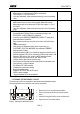
FULLTEST 3 4. OPERATING INSTRUCTIONS 4.1. INSTRUMENT - DESCRIPTION Figure 2: Instrument description LEGEND 1 Quick instruction label under the cover. 2 Fuse F3, type T12.5A/500V 6.3×32 mm which protects internal circuitry in LOOP, RA and RCD measurements. 3 General tester fuse F2, type T16A/250V 5×20 mm which protects internal circuitry in POWER, RPE and DIELECTRIC measurements. 4 General tester fuse F1, type T16A/250V 5×20 mm which protects internal circuitry in POWER, RPE and DIELECTRIC measurements.
FULLTEST 3 6 7 8 9 10 11 12 13 14 15 16 17 18 19 20 21 22 23 24 25 26 27 28 29 30 31 32 33 34 35 36 Connector for START/SAVE remote control adapter. Connector SAFETY INPUT for connection of external safety switch (for example protection door). It disables DIELECTRIC tests in case the switch is open. IEC female connector for connection of red WARNING LAMP in DIELECTRIC test. The lamp is active when the test is on (parallel operation to HV lamp on front panel, reference 35).
FULLTEST 3 4.3. MEASUREMENT FUNCTION SELECTION Press the FUNC hard key (yellow), the function selection screen will appear. RPE-2WIRE RCD POWER RPE-4WIRE LOOP PHASESEQ M RA ICLAMP DIELECT URES ILEAK Figure 3: Function selection screen Select wished function by pressing appropriate touch-screen key, basic measurement screen of selected function will appear, see an example of RPE-2WIRE basic measurement screen below. Other functions use adapted screens, but follow the same system.
FULLTEST 3 5. MEASUREMENTS 5.1. CONTINUITY - TWO WIRE METHOD (RPE-2WIRE) Complying with EN 60204-1, continuity of protective bonding circuit between PE terminal and relevant points of the protective conductor system must be checked by injecting a measurement current of 0.2 A up to 10 A approx. 5.1.1. RPE-2WIRE DISPLAY EXPLANATION Adjustable/selectable parameters: Im NOM - nominal measurement current 200 mA or 25 A AC LIMIT (meas. current 200 mA) - continuity limit value 0.01 19.99, 20.0 200.
FULLTEST 3 6 ..... LIMIT touch-screen key to select limit value (200 mA measurement) or limit mode (25 A measurement). Currently selected value or CALC is displayed on the bottom of the key. CALC message means the value is calculated. 7 ..... MODE touch-screen key to select operation mode (MANUAL or TIMER). Currently selected mode is displayed on the bottom of the key. TIMER mode is available in 200 mA measurement and in 25 A measurement if STANDARD limit mode is selected. 8 .....
FULLTEST 3 The following specific information may be shown on the display during calibration: Information displayed Description SHORTCIRCUIT TEST LEADS Calibration has been started (CAL touch-screen key has AND PRESS START KEY TO been pressed). CALIBRATE Shortcircuit test leads and press the START button! Test leads are opened after pressing the START button.
FULLTEST 3 5.1.4. RPE-2WIRE MEASUREMENT Measured quantities and display ranges: Resistance RPE 0 200 (nominal test current 200 mA) 0 20 (nominal test current 25 A) Measurement current Im 10 255 mA (nominal test current 200 mA) 0.2 30.0 A (nominal test current 25 A) 1) 2) 3) 4) 5) 6) 7) Select the RPE-2WIRE measurement by pressing the FUNC hard key first. Check selected test current (200 mA or 25 A) and modify it if needed by pressing the Im NOM (5) touch-screen key first.
FULLTEST 3 CAUTION Max external voltage between two RPE or between two SENSE test terminals is 10 VAC, no DC external voltage is allowed! In case of higher external voltage fuse F4 (T20A/500V, 6.
FULLTEST 3 5.2. CONTINUITY - FOUR WIRE METHOD (RPE-4WIRE) Complying with EN 60204-1, continuity of protective bonding circuit between PE terminal and relevant points of the protective conductor system must be checked by injecting a measurement current of 0.2 A up to 10 A approx. Limit values are the values which correspond to the length, cross section and material of measured conductor. 5.2.1.
FULLTEST 3 10 ... Set measurement time (in TIMER mode only). 11 ... Measurement result status (symbol in green colour - result OK, symbol result not OK). 5.2.2. CALIBRATION OF TEST LEADS The calibration is not needed because of 4-wire method.
FULLTEST 3 5.2.3. RPE-4WIRE MEASUREMENT Measured quantities and display ranges: Continuity RPE 0 20 Test current 0.2 30 A 1) 2) 3) 4) 5) Select the RPE-4WIRE function by pressing the FUNC hard key first. Check selected limit value and modify it if needed by pressing the LIMIT (6) touch-screen key first. Four independent preset limit values are available in STANDARD limit mode selection for quicker operations.
FULLTEST 3 7) with beep-beep sound (result OK) or with red symbol and with longer beep sound (result not OK). See the display outlook with test result on Figure 8. Save the test result by pressing the SAVE hard key twice, for further instructions see the “MEMORIZING EXAMPLE” section. CAUTION Max external voltage between two RPE or between two SENSE test terminals is 10 VAC, no DC external voltage is allowed! In case of higher external voltage fuse F4 (T20A/500V, 6.
FULLTEST 3 5.3. INSULATION RESISTANCE (M) • According to EN 60204-1, the insulation resistance between shorted active conductors of power circuit and the earth bonding system must be checked by applying a test voltage of 500 V DC. The limit value is 1 M. • Ensure that all switches on the unit under test are closed in order to test all it’s components. For purpose of the measurement, all active conductors (L1, L2, L3 and N) must be shortcircuited. 5.3.1.
FULLTEST 3 5.3.2. RISO MEASUREMENT Measured quantities and display ranges: Insulation resistance RINS 0 100 M (test voltage 100 V) 0 250 M (test voltage 250 V) 0 500 M (test voltage 500 V) 0 1000 M (test voltage 1000 V) Test voltage Utest 0 1100 V 1) 2) 3) 4) 5) 6) Select M function by pressing the FUNC hard key first. Check selected test voltage (100, 250, 500 or 1000V) and modify it if needed by pressing the Utest (5) touch-screen key first.
FULLTEST 3 CAUTION Connect COM test lead to chassis if the UUT is grounded. In case of reversed test leads measurement result may be affected by instrument’s internal resistance of 10 M! Due to the measurement of insulation resistance, capacitive UUT will be charged with test voltage. The UUT will be discharged after finishing the measurement via internal resistance of approx. 2 M. The UUT can retain dangerous voltage in case of premature removal of test leads.
FULLTEST 3 5.4. DIELECTRIC (DIELECTRIC) According to EN 60204-1, electric equipment must withstand a voltage test between shorcircuited active conductors of power circuit and the earth bonding system for approx. 1 s. The test shall be carried out at twice the rated supply (or 1000 V whichever is greater) 50 Hz. Components not rated for this test voltage may be disconnected before carrying out the test. 5.4.1.
FULLTEST 3 5.4.2. DIELECTRIC DISPLAY EXPLANATION Adjustable/selectable parameters: MODE - operation mode UTEST NOM - nominal test voltage LIMIT - current limit CHAR - current character MANUAL, RAMP or BURN 250 5100 V AC 1 110 mA IAPP or IREAL Figure 13: Display with DIELECTRIC test result 1 ..... Selected function. 2 ..... Progress bar, it follows test time during the measurement (in RAMP mode only). 3 ..... Test voltage applied during the measurement. 4 ..... Measurement screen touch-screen key. 5 ..
FULLTEST 3 5.4.3. DIELECTRIC TEST Measured quantities and display ranges: Apparent leakage current IAPP 0 200 mA 0 200 mA Real leakage current IREAL Test voltage 250 5.
FULLTEST 3 Figure 16: Connection of test leads 8) Carry out the test by pressing the START/STOP button. Warning with explanation of how to connect test leads with regard to selected test voltage will be displayed. Check the connection then confirm it by pressing the YES touch-screen key, the message “READY” will appear and will stay present for 10 seconds. START/STOP button is active while “READY” message is present.
FULLTEST 3 5.5. RCD (RCD) 5.5.1. RCD DISPLAY EXPLANATION Adjustable/selectable parameters: TYPE - type of RCD CHARACTERISTIC - RCD characteristic IN - nominal differential current MEAS - type of measurement POL - test current polarity DELAY – delay time in DELAY characteristic AC, A or B GENERAL, SELECTIVE or DELAYED 10, 30, 100, 300, 500, 650 or 1000 mA t/1/2IN, t/IN, t/2IN, t/5IN, I or AUTO POS (positive) or NEG (negative) 0 700 ms Figure 17: Display with RCD test result 1 .....
FULLTEST 3 5.5.2. EXPLANATION OF RCD TEST CURRENTS See the figures below for test current shapes with regard to selected RCD type and test current polarity.
FULLTEST 3 5.5.3.
FULLTEST 3 READY message will appear as soon as the tester is properly connected to the installation and mains voltage is present, see the “Input conditions” above. 8) Carry out the measurement by pressing the START button. 9) Test result will be displayed in green colour equipped with green symbol and with beep-beep sound if it is within limit range, see the table of allowed trip out times below.
FULLTEST 3 5.6. LOOP IMPEDANCE / SHORT-CIRCUIT CURRENT (LOOP) • According to EN 60204-1, the conditions for protection against electric shock in installations with automatic disconnection of mains voltage are: • Measurement or evaluation of fault loop impedance and testing the over-current protection device involved in the fault loop. • Limit values are shown in the Table 10 of EN 60204-1. 5.6.1.
FULLTEST 3 9 ..... WIRE touch-screen key to select the material of measured wire (Cu or Al), coating (PVC, BUTYL RUBBER or EPR/XLPE), section (1, 1.5, 2.5, 4, 6, 10, 16, 25, 35, 50 or 70 mm2) and number of conductors (1 99). Currently selected material is displayed on the bottom of the key. 10 ... Measurement result (in green colour - result OK, in red colour - result not OK). 11 ... Real time clock (hh.mm.ss). 12 ... Unit of the test result (). 13 ...
FULLTEST 3 - Tset (max trip time) - 2, 4, 6, 8, 10, 12, 16, 20, 25, 32, 40, 50, 63, 80, 100, 125, 160, 200, 250, 315, 400, 500, 630, 800, 1000 or 1250 A (FUSE gG) - 2, 4, 6, 8, 10, 12, 16, 20, 25, 32, 40, 50, 63, 80, 100, 125, 160, 200, 250, 315, 400, 500 or 630 A (FUSE aM) 0.1, 0.2, 0.4 or 5 s Ut - verification if short-circuit current is high enough over-current protection device to react within set time.
FULLTEST 3 Where: T ... Trip out time according to the characteristic and nominal current of used protection device K ... See the table below Material / Coating PVC Natural / Butyl rubber EPR/XLPE Cu (Copper) K = 115 K = 135 K = 143 Al (Aluminium) K = 76 K = 87 K = 94 N ... Number of conductors S ... Cross section of a conductor For calculation of short-circuit current ISC nominal voltage Un of mains installation is needed, so it must be selected in prior to the measurements.
FULLTEST 3 Figure 23: Connection of test cable to schuko socket for LOOPL/N or LOOPL/PE measurement Figure 24: Connection of test leads to tested wiring for LOOPL/N measurement Figure 25: Connection of test leads to tested wiring for LOOPL/L measurement EN - 37
FULLTEST 3 Figure 26: Connection of test leads to tested wiring for LOOPL/PE measurement 7) READY message will appear when mains voltage UL/N (LOOP L/N) or UL/PE (LOOP L/PE) within 100 265 V or UL/L (LOOP L/L) within 100 460 V is present. Carry out the measurement by pressing the START button. 8) Test result (loop impedance) will be displayed in green colour equipped with green symbol and with beep-beep sound if measured/calculated ISC corresponds to entered limit mode and other entered parameters.
FULLTEST 3 5.7. GLOBAL EARTH RESISTANCE / CONTACT VOLTAGE (RA) • According to EN 60204-1, the conditions for protection against electric shock in installations with automatic disconnection of mains voltage are: • Measurement or evaluation of fault loop impedance and testing the over-current protection device involved in the fault loop. • Limit values are shown in the Table 10 of EN 60204-1. 5.7.1.
FULLTEST 3 5.7.3. RA MEASUREMENT Measured quantities and display ranges: Global earth resistance RA 0 2.000 (IN = 10 or 30 mA) 0 1.
FULLTEST 3 5) Carry out the measurement by pressing the START/STOP button. Test result will be displayed after elapsing measurement time in green colour equipped with green symbol and with beepbeep sound if it is lower than or equal to limit value (see the explanation of limit value above). If the result is higher than limit value, then it will be displayed in red colour equipped with red symbol and with longer beep sound. See the display outlook with test result on the figure 27.
FULLTEST 3 5.8. RESIDUAL VOLTAGE (URES) • What are residual voltages? Residual voltages are the voltages that remain present even after switching off a machine or device. This can be caused e.g. by built in capacitors or subsequent generators. This measurement is performed by using the URES function. • According to EN 60204-1, accessible live parts connected to dangerous voltage must discharge within 5 seconds (permanently connected machines) or within 1 second (plugged-in machines) down to 60 V.
FULLTEST 3 To include standard mains over-voltage, the measured residual voltage is scaled to peak value of max. possible mains over-voltage, i.e.: a) Selected nominal voltage Un = 230 V Up = 230 V × 1.1 × 1.41 = 358 V ....................... system voltage 230 V is recognized Up = 400 V × 1.1 × 1.41 = 620 V ....................... system voltage 400 V is recognized b) Selected nominal voltage Un = 240 V Up = 240 V × 1.1 × 1.41 = 372 V .......................
FULLTEST 3 5.8.3. URES DISPLAY EXPLANATION Selectable parameters: MODE - measurement mode CON - connection LIMIT t - limit time LINEAR or NONLINEAR INT (measurement on internal components) or PLUG (measurement on 1P/3P plug) 1 s or 5 s Figure 32: Display with URES test result 1 ..... Selected function. 2 ..... Input voltage UIN and trigger voltage UTRIG. 3 ..... Measurement screen touch-screen key. 4 ..... MODE touch-screen key to select measurement mode (LINEAR or NONLINEAR).
FULLTEST 3 5.8.5. URES MEASUREMENT Measured quantities and display ranges: Residual voltage on power plug URES 10 460 V AC or 10 650 V DC Residual voltage on internal components URES 10 460 V AC or 10 650 V DC Input requirements: Input voltage UIN (READY condition in PLUG mode) 43 460 V AC Trigger voltage UTRIG (READY condition in INT mode) 100 460 V AC 1) 2) 3) Select URES function by pressing the FUNC key first.
FULLTEST 3 8) Test result will be displayed in green colour equipped with green symbol and with beep-beep sound if it is lower than or equal to 60 VRMS (may be AC or DC, see the unit). If the result is higher than 60 VRMS, then it will be displayed in red colour equipped with red symbol and with longer beep sound. See the display outlook with test result on the figure 32. 9) Save the test result by pressing the SAVE hard key twice, for further instructions see the “MEMORIZING EXAMPLE” section.
FULLTEST 3 The following specific information can be shown on the display during the measurement: Information displayed LOW TRIGGER VOLTAGE REPEAT LOW SWITCH-OFF VOLTAGE REPEAT Description Mains voltage was disconnected at too low momentary voltage (< 20% of peak value). The message may appear in LINEAR mode only. Repeat the measurement (connect and disconnect the UUT again)! Mains voltage was not disconnected close enough to peak value (Up ± 5%) so the result would be irelevant anyway.
FULLTEST 3 5.9. POWER (POWER) Measured appliance is supplied by mains voltage applied to schuko test socket. Switching the voltage on/off as well as selection of phase position is done by internal switch of the tester. 5.9.1. POWER DISPLAY EXPLANATION Adjustable/selectable parameters: TIMER - measurement time LIMIT - limit value of apparent power L POS - position of phase terminal on schuko socket 00:05 60:00, resolution 1 s 6 VA 5.06 kVA LEFT or RIGHT Figure 36: Display with POWER test result 1 .....
FULLTEST 3 5.9.2. POWER MEASUREMENT Measured quantities and display ranges: Apparent power PAPP 0 5.06 kVA Real power P 0 5.06 kVA Mains voltage UL/N 195 253 V 0 20 A Load current IL Power factor PF 01 0.25 mA 10 A Leakage current IPE 1) 2) 3) 4) 5) 6) Select POWER function by pressing the FUNC hard key first. Check selected measurement time and modify it if needed by pressing the MODE (5) touch-screen key first. Four independent preset measurement times are available for quicker operations.
FULLTEST 3 CAUTION Measurement at both phase positions (phase at left terminal and phase at right terminal) must be carried out when leakage current IPE is measured and the highest value must be evaluated. Switch on the UUT in order full power of the unit and total leakage current to be measured! In case of overloaded test socket the fuse F1 or F2 (both T16A/250V) may blow.
FULLTEST 3 5.10. PHASE SEQUENCE (PHASESEQ) Correct phase sequence is important when e.g. 3-phase machines with mechanical rotation are connected to 3-phase mains installation. 5.10.1. PHASE SEQUENCE DISPLAY EXPLANATION Adjustable/selectable parameters: There are no adjustable/selectable parameters available! Figure 38: Display with PHASE SEQUENCE test result 1 ..... Selected function. 2 .....
FULLTEST 3 5.10.2. PHASE SEQUENCE MEASUREMENT Measured quantities and display ranges: Phase sequence 1.2.3. or 2.1.3. Phase-to-phase voltage UL1/2 360 460 V Phase-to-phase voltage UL2/3 360 460 V 360 460 V Phase-to-phase voltage UL3/1 1) 2) Select the PHASESEQ function by pressing the FUNC hard key first. Connect the test leads to tested socket/wiring according to the figure below.
FULLTEST 3 5.11. CURRENT MEASUREMENT USING CURRENT CLAMP (ICLAMP) 5.11.1. ICLAMP DISPLAY EXPLANATION Adjustable/selectable parameters: RANGE - measurement range LIMIT - limit value 1000 mA, 100 A or 1000 A 0.1 1000 mA (range 1000 mA) 0.1 100.0 A (range 100.0 A) 1 1000 A (range 1000 A) Figure 40: Display with ICLAMP test result 1 ..... Selected function. 2 ..... Measurement screen touch-screen key. 3 ..... RANGE touch-screen key to select measurement range (0 1000 mA, 0 100 A or 0 1000 A).
FULLTEST 3 5.11.2. ICLAMP MEASUREMENT Measured quantities and display ranges: Clamp current ICLAMP 0 1000 mA (range 1000 mA) 0 100 A (range 100 A) 0 1000 A (range 1000 A) 1) 2) 3) 4) 5) Select ICLAMP function by pressing the FUNC hard key first. Check selected measurement range and modify it if needed by pressing the RANGE (3) touchscreen key first. Check selected limit current and modify it if needed by pressing the LIMIT (4) touch-screen key first.
FULLTEST 3 5.12. LEAKAGE CURRENT (ILEAK) 5.12.1. LEAKAGE DISPLAY EXPLANATION Adjustable/selectable parameters: MODE - measurement mode LIMIT - leakage current limit value CLAMP or SOCKET 0.1 100.0 mA, 101 1000 mA (CLAMP mode, range 1000 mA) 0.1 100.0 A (CLAMP mode, range 100.0 A) 1 1000 A (CLAMP mode, range 1000 A) 0.01 19.99 mA, 20.0 49.9 mA, 0.05 0.99 A, 1.0 10.0 A (SOCKET mode) RANGE - clamp measurement range 1000 mA, 100.
FULLTEST 3 Figure 43: Display with ILEAK test result in SOCKET mode 1 ..... Selected function. 2 ..... Sub-result, mains voltage UL/N. 3 ..... Measurement screen touch-screen key. 4 ..... MODE touch-screen key to select measurement mode (SOCKET or CLAMP). Currently selected mode is displayed on the bottom of the key. 5 ..... LIMIT touch-screen key to select limit leakage current. Currently selected value is displayed on the bottom of the key. 6 .....
FULLTEST 3 5.12.2. LEAKAGE CURRENT MEASUREMENT USING CURRENT CLAMP Measured quantities and display ranges: Leakage current ILEAK measured by clamp 1) 2) 3) 4) 5) 6) 0 1000 mA (1000 mA range) 0 100 A (100 A range) 0 1000 A (1000 A range) Select ILEAK function by pressing the FUNC hard key first. Select CLAMP mode by pressing the MODE touch-screen key first. Check selected measurement range and modify it if needed by pressing the RANGE (4) touchscreen key first.
FULLTEST 3 5.12.3. LEAKAGE CURRENT MEASUREMENT ON SCHUKO SOCKET Measured quantities and display ranges: Leakage current IPE on schuko socket Mains voltage UL/N 1) 2) 3) 4) 5) 6) 0.25 mA 10 A 195 253 V Select ILEAK measurement by pressing the FUNC hard key first. Select SOCKET mode by pressing the MODE touch-screen key first. Check selected limit leakage current by pressing the LIMIT (5) touch-screen key first. Four independent limit values are available for quicker operations.
FULLTEST 3 The following specific information can be shown on the display during the measurement: Information displayed Description IPE CURRENT OVERRANGE! If IPE current is higher than 10 A for 10 s, the measurement will be stopped and this message will appear. IL CURRENT OVERRANGE! If IL current is higher than 16 A for 10 s, the measurement will be stopped and this message will appear.
FULLTEST 3 6. MENU FUNCTIONS For further selection, entry and display of instrument’s settings press the MENU hard key, the following MAIN MENU will appear. MAIN MENU MEMORY LANGUAGE SETUP OPERATOR TESTER INFO SOUND Figure 46: MAIN MENU Press wished submenu touch-screen key for further settings. 6.1. MEMORY menu MEMORY MEM INFO CLEAR USB Figure 47: MEMORY menu 6.1.1.
FULLTEST 3 6.1.2. CLEAR menu In order to clear saved results the CLEAR menu shall be used. CLEAR TOTAL LAST RESULT Figure 49: CLEAR menu The whole memory (TOTAL) or only the last saved result (LAST RESULT) can be cleared. If the last result is cleared, then the result saved before the last one become to be the last and can be cleared too etc. Confirm clearing operation by pressing the YES touch-screen key. 6.1.3.
FULLTEST 3 Figure 51: ADD OPERATOR menu - Create new operator’s name. Use the 123 / ABC key to select figure or character selection screen. - Confirm entered name by pressing the ENTER touch-screen key. OPERATOR screen will appear again and last entered operator will be selected. How to delete an operator: - Open OPERATOR menu, select the operator you wish to delete and press the DELETE touchscreen key. Confirm the deletion by pressing the YES touch-screen key. 6.3.
FULLTEST 3 6.5. SETUP menu SETUP LEVEL NAMES DATE/TIME NOMINAL VOL. CONTACT VOL. SAFET INPUT RESET Figure 54: SETUP menu 6.5.1. LEVEL NAMES menu Three levels are available when saving test results i.e. LEVEL1, LEVEL2 and LEVEL3. In production the three levels are dedicated to CUSTOMER, LOCATION and MACHINE, but operator can rename them freely for example to DEVICE, DEPARTMENT and LOCATION. In order to do this the LEVEL NAMES menu shall be used.
FULLTEST 3 6.5.2. LIMIT CONTACT VOLTAGE menu This menu shall be used in order to select limit contact voltage which is used in RCD and in RA measurements. The voltage may be either 25 or 50 V. CONTACT VOL. 25 V 50 V Figure 57: CONTACT VOL. menu Select wished limit contact voltage by pressing appropriate touch-screen key, the menu will turn to SETUP menu. 6.5.3. DATE/TIME menu In order to set date and time DATE/TIME menu shall be used.
FULLTEST 3 The following parameters have been reset. Function GENERAL RPE-2WIRE Parameter - OPERATOR = Default - LANGUAGE = ITALIAN - CONTACT VOLTAGE = 50 V - NOMINAL VOLTAGE = 230 V - SAFETY INPUT = ENABLED - SOUND = ON - Im NOM = 200 mA - LIMIT value (200 mA) = 0.30 - MODE = MANUAL - CAL (200 mA) = 0.00 - LIMIT value 1 (200 mA) = 0.30 LIMIT value 2 (200 mA) = 1.00 LIMIT value 3 (200 mA) = 5.00 LIMIT value 4 (200 mA) = 50.
FULLTEST 3 RPE-4WIRE RISO - LIMIT value (STANDARD limit mode) = 0.300 - MODE MANUAL - LIMIT value 1 (STANDARD limit mode) = 0.300 LIMIT value 2 (STANDARD limit mode) = 1.000 LIMIT value 3 (STANDARD limit mode) = 5.00 LIMIT value 4 (STANDARD limit mode) = 10.00 LENGTH = 2 m LENGTH 1 = 2 m LENGTH 2 = 3 m LENGTH 3 = 10 m LENGTH 4 = 100 m SECTION = 1 mm2 SECTION 1 = 1 mm2 SECTION 2 = 2.5 mm2 SECTION 3 = 10 mm2 SECTION 4 = 35 mm2 MAT. = Cu Z LINE = 0.100 ZLINE 1 = 0.100 ZLINE 2 = 0.
FULLTEST 3 DIELECTRIC RCD LOOP RA URES - MODE = MANUAL UTEST NOM = 250 V LIMIT value = 1 mA CHAR = IAPP - UTEST NOM 1 = 250 V UTEST NOM 2 = 1000 V UTEST NOM 3 = 2500 V UTEST NOM 4 = 3500 V RAMP TIMER = 10 s RAMP TIMER 1 = 10 s RAMP TIMER 2 = 30 s RAMP TIMER 3 = 1 min RAMP TIMER 4 = 10 min LIMIT value 1 = 1 mA LIMIT value 2 = 10 mA LIMIT value 3 = 50 mA LIMIT value 4 = 100 mA TYPE = AC GEN IN = 30 mA MEAS = t/IN POL = POS - DELAY = 100 ms DELAY 1 = 100 ms DELAY 2 = 200 ms DELAY 3 = 300 ms DELAY 4
FULLTEST 3 POWER PHASE ROTATION ICLAMP ILEAK - TIMER = 10 s - LIMIT apparent power = 6 VA - L POS = RIGHT - TIMER 1 = 10 s TIMER 2 = 30 s TIMER 3 = 1 min TIMER 4 = 10 min LIMIT apparent power 1 = 6 VA LIMIT apparent power 2 = 100 VA LIMIT apparent power 3 = 1.00 kVA LIMIT apparent power 4 = 5.06 kVA None RANGE = 1000 mA LIMIT value (range 1000 mA) = 3.5 mA - LIMIT value 1 (range 1000 mA) = 3.5 mA LIMIT value 2 (range 1000 mA) = 10.
FULLTEST 3 6.5.5. NOMINAL VOLTAGE menu This menu shall be used in order to select nominal mains voltage. The voltage may be either 230 or 240 V. It is used in LOOP and URES measurements. In LOOP measurements it is used for calculation of prospective short-circuit current, see the “LOOP IMPEDANCE / SHORT-CIRCUIT CURRENT (LOOP)” section. In URES function (linear mode only) the nominal voltage is used for scaling of measured value, see the “RESIDUAL VOLTAGE (URES)” section. NOMINAL VOL.
FULLTEST 3 6.6. SOUND menu In order to turn the acoustic signals off/on SOUND menu shall be used. SOUND OFF ON Figure 61: SOUND menu Select the SOUND status by pressing appropriate touch-screen key, screen will turn to SETUP menu.
FULLTEST 3 7. MEMORY FEATURES Any memory address consists of three levels i.e. LEVEL 1 (in production set to CUSTOMER), LEVEL 2 (in production set to LOCATION) and LEVEL 3 (in production set to MACHINE). The memory address (at least LEVEL 1 i.e. CUSTOMER) should be entered after the first pressing the SAVE hard key. Additionally comment can be added to each saved result. Once the address is entered, it will be offered any time when save operation is activated.
FULLTEST 3 8. MEMORIZING EXAMPLE In order to save measurement result to a particular storage address, follow the next steps: 1) 2) Carry out the measurement. Press the SAVE hard key, the following display will appear (example): SAVE CUSTOMER COMPANY A LOCATION ROMA MACHINE PLASTIC INJECTION MACHINE No 003 COMMENT DEVICE SERVICED Figure 63: SAVE menu 3) Confirm the save operation by pressing the SAVE hard key again if offered address (CUSTOMER, LOCATION and MACHINE) as well as COMMENT are OK.
FULLTEST 3 Figure 65: ADD CUSTOMER menu - Create new customer’s name. Use the 123 / ABC key to select figure or character selection screen. - Confirm entered name by pressing the ENTER touch-screen key, SAVE – SELECT CUSTOMER screen will appear again and last entered operator will be selected. Press the ENTER touch-screen key to confirm selected customer, SAVE menu will be offered again. Repeat the operation for the other two levels and for comment if needed following the same procedure.
FULLTEST 3 9. RECALL RESULTS In order to recall saved measurement result, follow the next steps: 1) Press the RCL hard key, the following screen will appear. Figure 66: RECALL menu 2) Check offered customer and if needed, select another one by pressing the CUSTOMER touchscreen key first. The following screen will appear. Figure 67: RECALL - SELECT CUSTOMER menu - Check the list of available customers by using the ▼ and ▲ touch-screen keys (if there are more than 4 customers entered).
FULLTEST 3 Figure 68: ILEAK function RECALL screen 5) Press the RCL hard key again in order to check next screens.
FULLTEST 3 10. ENTRY OF DATA BY USING AN EXTERNAL KEYBOARD The optional USB keyboard is a welcome accessory when inserting memory address construction (customer, machine and location) as well as comment, in order to do the job quickly and simply. Connect the USB keyboard to USB2 or USB3 connector, three sound signals will follow after plugging it, as a confirmation of USB-device recognition. Now, the external keyboard is operational. 11.
FULLTEST 3 Fuse replacement (fuse F1, F2) The two fuses are general ones for the tester and protect internal circuitry in POWER, RPE and DIELECTRIC measurements. In case mains switch pilot lamp (5) does not illuminate after connecting the Machinery-Tester FULLTEST 3 to mains outlet and switching on the mains switch and neither the LC-Display (24) shows any indication, it is very likely mains fuse F1 (4) or F2 (3) or both to be blown.
FULLTEST 3 14. TECHNICAL SPECIFICATIONS 14.1. MEASUREMENT FUNCTIONS CONTINUITY OF PROTECTIVE CONDUCTOR (RPE-2WIRE, 0.2A) Display range Resolution Accuracy () (M) 0.01 0.00 19.99 ± (3% rdg. + 3 dgt) 0.1 20.0 200.0 Standard test leads: Open-circuit test voltage: Short-circuit test current: Test current: Display range of test current: Accuracy of displayed test current: Limit value: Measurement principle: Test lead calibration: Protection against ext.
FULLTEST 3 Continuity of protective conductor (RPE-4WIRE, 25A) Display range Resolution () (M) 0.001 0.000 1.999 0.01 2.00 20.00 Standard test leads: Open-circuit test voltage: Short-circuit test current: Test current (25A range): Display range of test current: Accuracy of displayed test current: Limit value: Measurement principle: Protection against ext. voltage: Detection of external voltage Accuracy Overvoltage protection ± (3% rdg. + 3 dgt) CAT III 300 V 2 × 2 m, 2.5 mm2 Approx. 4.
FULLTEST 3 Insulation resistance (M) DC test voltage Display range (V) (M) 0.00 9.99 100 10.0 20.0 20.0 99.9 0.00 9.99 10.0 20.0 250 20.0 99.9 100 250 0.00 9.99 10.0 20.0 500 20.0 99.9 100 500 0.00 9.99 10.0 20.0 1000 20.0 99.9 100 1000 Test voltage tolerance: Test current: Short-circuit current: Discharge: Detection of external voltage Resolution (M) 0.01 0.1 0.1 0.01 0.1 0.1 1 0.01 0.1 0.1 1 0.01 0.1 0.1 1 Accuracy Overvoltage protection ± (3% rdg. + 3 dgt) ± 5% rdg.
FULLTEST 3 Dielectric withstanding test (DIELECTRIC) Nominal test Output voltage UN (V) 250 800 COM & 0.250.80 kV 810 2500 COM & 0.812.50 kV 2510 5100 COM & 2.515.10 kV Nominal test voltage UN: Distortion of test voltage: Measurement modes: Output power: Resolution (V) Accuracy of output voltage Overvoltage protection 10 ± 3% UN CAT III 300 V Adjustable 250 5100 V, 50/60 Hz (floating) in steps of 10 V Crest factor = 1.
FULLTEST 3 RCD test (RCD) RCD types / characteristics: Measurement modes: AC, A or B / General, Selective or Delayed x1/2IN, x1IN, x2IN, xKIN (K = 4 B type, K=5 AC, A type), I (RAMP), AUTO (sequence: x1/2, x1, xK) Nominal currents: 10, 30, 100, 300, 500, 650 or 1000 mA Accuracy of test currents (10 mA): - 10% / + 0% (IN/2) + 10% / - 0% (IN, 2IN, KIN) Accuracy of test currents (301000 mA): - 5% / + 0% (IN/2) + 5% / - 0% (IN, 2IN, KIN) Input voltage range / frequency: 100 265 V / (50 / 60 Hz
FULLTEST 3 LOOP impedance / Short-circuit current (LOOP) Display range Resolution () (M) 0.001 *0.000 2.000 0.01 0.00 9.99 0.1 10.0 99.9 1 100 200 * With optional accessory IMP57 only! Input voltage range LOOP L/PE or L/N: Input voltage range LOOP L/L: Nominal mains voltage: Loading resistance: ISC calculation: Short-circuit current ISC: Display range (A) 0.05 0.99 1.0 99.9 100 999 1.00k 46.00k Accuracy Overvoltage protection ± (3% rdg.
FULLTEST 3 Global earth resistance without tripping RCD (RA) IN Display range RA Resolution Accuracy (mA) () () 10 1 0 2000 ± (3% rdg. + 1 ), 15 2000 * 0.1 0.0 99.9 30 ± (3% rdg. + 1 ), 10 2000 * 1 100 2000 0.1 0.0 99.9 100 1 100 1000 0.1 0.0 99.9 300 1 100 300 0.1 ± (3% rdg. + 3 dgt)* 0.0 99.9 500 1 100 200 0.1 0.0 99.9 650 1 100 150 1000 0.1 0.0 100.
FULLTEST 3 TRMS Residual voltage (URES) Display range Resolution (V) Accuracy (general) Overvoltage protection 10 460 10 650 1 ± (3% rdg. + 3 V) CAT III 300 V 0 460 VAC 230 or 240 V 4-wire connection (INTERNAL measurement, 1 s or 5 s) 2-wire connection (PLUG measurement, 1 s) 60 V RMS Input voltage (UTRIG): Nominal mains voltage: Measurement method: Residual voltage limit value: Input voltage URES: Display range (V) 10 460 VAC 10 650 VDC Resolution (V) Accuracy 1 ± (2% rdg.
FULLTEST 3 TRMS Load Current (POWER) Display range Resolution A A 0.01 0.00 0.99 0.1 1.0 20.0 Pre-Test TRMS Mains Voltage (POWER) Display range Resolution V V 1 195 253 Apparent Power / Active Power (POWER) Display range Resolution VA/W VA/W 0.1 0.0 99.9 1 100 999 10 1.00 5.06 k TRMS Leakage Current IPE (POWER) Display range Resolution 0.01 mA 0.25 19.99 mA 0.1 mA 20.0 49.9 mA 0.01 A 0.05 0.99 A 0.1 A 1.0 10.
FULLTEST 3 PHASE SEQUENCE (PHASESEQ) Display range Resolution UL1/2, UL2/3, UL3/1 (V) (V) 1 360 460 Display of test result: Accuracy Overvoltage protection ± (2% rdg. + 2 dgt) CAT III 300 V 1.2.3 (right) or 2.1.3 (left) or 1.1.X (not defined) TRMS Clamp Current (ICLAMP) Display range Resolution Accuracy (w/o clamp error) Overvoltage protection 0.0 99.9 mA 100 1000 mA 0.00 9.99 A 10.0 100.0 A 0.0 99.9 A 100 1000 A 0.1 mA 1 mA 0.01 A 0.1 A 0.1 A 1A ± (3% rdg.
FULLTEST 3 TRMS Leakage current using current clamp (ILEAK) Display range Resolution Accuracy (w/o clamp error) Overvoltage protection 0.0 99.9 mA 100 1000 mA 0.00 9.99 A 10.0 100.0 A 0.0 99.9 A 100 1000 A 0.1 mA 1 mA 0.01 A 0.1 A 0.1 A 1A ± (3% rdg. + 3 dgt) One measurement terminal grounded Range 1000 mA 100.0 A 1000 A Input voltage range: Input resistance: Frequency range: Clamp type: LIM value (1000 mA range): LIM value (100.
FULLTEST 3 14.2. GENERAL SPECIFICATION POWER SUPPLY Mains voltage: Current consumption: 207 253 V / 50/60 Hz ± 5% 16 Amax MECHANICAL SPECIFICATIONS Dimensions (L x W x H): Weight: 400 x 300 x 170 mm 15 kg MEMORY AND INPUT/OUTPUT INTERFACES Internal memory: 999 locations (three-level memory structure) PC interface: USB 2.0 device, connector type “B” USB keyboard, USB printer, pen drive, USB barcode reader: 2 x USB 2.
FULLTEST 3 15. SERVICE 15.1. WARRANTY CONDITIONS This instrument is guaranteed against material or production defects, in accordance with our general sales conditions. During the warranty period the manufacturer reserves the right to decide either to repair or replace the product. Should you need for any reason to return back the instrument for repair or replacement take prior agreements with the local distributor from whom you bought it.
Via della Boaria 40 48018 – Faenza (RA)- Italy Tel: +39-0546-621002 (4 linee r.a.) Fax: +39-0546-621144 Email: ht@htitalia.it http://www.ht-instruments.