User manual M72 – M73 – M 74 – M75 Copyright HT ITALIA 2013 Release EN 3.
M72 - M73 - M74 - M75 Table of contents 1. SAFETY PRECAUTIONS AND PROCEDURES ...................................................................... 2 1.1. 1.2. 1.3. 1.4. 2. GENERAL DESCRIPTION ....................................................................................................... 4 2.1. 2.2. 2.3. 3. Features ...........................................................................................................................................
M72 - M73 - M74 - M75 1. SAFETY PRECAUTIONS AND PROCEDURES This instrument complies with safety Standards IEC/EN61557-1 and IEC/EN61010-1 related to electronic measuring instruments. CAUTION For your own safety and to avoid damaging the instrument follow the procedures described in this instruction manual and read carefully all notes preceded by this symbol .
M72 - M73 - M74 - M75 1.2. DURING USE CAUTION An improper use may damage the instrument and/or its components or injure the operator. Before selecting any function, first disconnect the test leads from the circuit under test When the instrument is connected to circuits never touch any unused terminal Do not measure resistance in presence of external voltages; although the instrument is protected, an excessive voltage may cause malfunctioning.
M72 - M73 - M74 - M75 2. GENERAL DESCRIPTION Dear Customer, the instrument you have purchased, whether used according to the instructions given in this manual, will grant you accurate and reliable measurements. Thanks to a development of newest conception assuring double insulation and overvoltage category III you will enjoy the highest safety. This manual refers to the entire range of Multitest family including M72, M73, M74 e M75 models.
M72 - M73 - M74 - M75 3. PREPARATION FOR USE 3.1. PRELIMINARY CHECKS This instrument was checked both mechanically and electrically prior to shipment. All possible cares and precautions were taken to let you receive the instrument in perfect conditions. Notwithstanding we suggest you to check it rapidly (eventual damages may have occurred during transport – if so please contact the local distributor from whom you bought the item). Make sure that all standard accessories mentioned in § 6.4 are included.
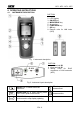
M72 - M73 - M74 - M75 4. OPERATING INSTRUCTIONS 4.1. INSTRUMENT DESCRIPTION CAPTION: 1. Inputs 2. LCD Display 3. ON/OFF key 4. MODE/PEAK key 5. Arrows key 6. FUNC/HOLD key 7. GO key 8. Remote units for LAN tests (M75) Fig. 1: Instrument description CAPTION: 1. Input terminal B2 2. Input terminal B1 3. Sliding cover for RJ45 connectors of LAN networks (M75) Fig.
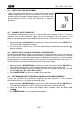
M72 - M73 - M74 - M75 4.2. SWITCH ON THE INSTRUMENT When the instrument is turned on, it emits a brief sound and all display segments are lit for just one second. Then the model number and the firmware release appear on the display (see picture referred to M75). Finally the instrument is ready for operation. 4.3. DISABLE AUTO POWER OFF The instrument automatically turns off 10 minutes after last pressure of keys. To resume operation turn on the instrument again.
M72 - M73 - M74 - M75 4.6. HOLD, MAX/MIN/AVG, PEAK± The following functions are available for measurements of AC and DC voltage, AC current, frequency and resistance. 4.6.1. HOLD The HOLD function permits to block on the display the detected value during measurements of AC and DC voltage, AC and DC current, frequency and resistance. Just press FUNC/HOLD for at least one second. The symbol HOLD is displayed. To escape this function press again FUNC/HOLD or the arrow keys.
M72 - M73 - M74 - M75 4.7. V HZ: DC/AC VOLTAGE AND FREQUENCY MEASUREMENT CAUTION The maximum input voltage is 550+10%V. Don’t try to measure higher voltages to avoid risks of electrical shocks or serious damages to the instrument. Fig. 3: Connection of the instrument’s terminals during V Hz test 1. Turn on the instrument 2. Press the arrow keys to select V 3. Insert the black and green cables in the corresponding input terminals of the instrument 4.
M72 - M73 - M74 - M75 8. Example of display of DC voltage. The minimum reading limit of DC voltage is 1.2V. Lower input values are displayed as 0.0V 9. Press MODE/PEAK for less than 1 second to pass to frequency measurement (only during AC measurement) DC voltage value 10. Press MODE/PEAK for more than 1 second to detect the voltage peak value (see § 4.6.3) 11. Press FUNC/HOLD for less than 1 second to block the detected values on the display (see § 4.6.1) 12.
M72 - M73 - M74 - M75 4.7.1. Anomalous cases which may occur during V 1. The maximum input voltage is 550+10%V. If the detected voltage value exceeds 605V TRMS the instrument displays the screen beside. Disconnect immediately the instrument from the circuit under test to avoid electrical shocks and damages to the instrument 2. If during a voltage measurement the detected frequency value exceeds 400Hz the instrument displays the screen beside 3.
M72 - M73 - M74 - M75 4.8. A HZ: DC/AC CURRENT AND FREQUENCY MEASUREMENT Fig. 4: Connection of the instrument’s terminals during A Hz test 1. Turn on the instrument 2. Press the arrow keys to select A 3. Insert the banana connectors of the clamp transducer in the corresponding input terminals of the instrument (black with black, green or red with green). For transducers with FRB hypertac connector is necessary the NOCANBA optional accessory 4.
M72 - M73 - M74 - M75 8. Example of AC current displaying. The minimum limit of AC current is: 1.0mV x transduction ratio of the clamp lower values are nullified. AC current value Frequency value The minimum reading value of AC and DC current is given by the herewith: 1mV x transduction ratio of the clamp Therefore, with a clamp 400A/400mV, the minimum measurable current is 1.0A. Lower input values are displayed as 0.0A 9.
M72 - M73 - M74 - M75 4.8.1. Anomalous cases which may occur during A 1. If the detected current value exceeds the clamp full scale the instrument displays the screen beside. Disconnect immediately the clamp from the circuit under test to avoid electrical shocks and damages to the instrument The instrument is 20% overchargeable than the clamp full scale 2. If during a current measurement the detected frequency value exceeds 400Hz the instrument displays the screen beside 3.
M72 - M73 - M74 - M75 4.9. : RESISTANCE MEASUREMENT AND CONTINUITY TEST CAUTION Before taking resistance measurements make sure that the circuit under test is not powered and that eventual condensers are discharged. Fig. 5: Connection of the instrument’s terminals 1. Turn on the instrument 2. Press the arrow keys to select 3. If the measuring cables being used have not been calibrated, first calibrate them as described in § 4.9.1 4.
M72 - M73 - M74 - M75 Fig. 6: Connection of the instrument’s terminals during calibration procedure 3. Press MODE/PEAK for more than 1 second. The instrument resets the resistance of the cables, the symbol "CAL" is displayed CAUTION While MODE/PEAK is pressed the instrument is measuring. During this phase never disconnect test leads. 4. The instrument performs the calibration of cables with resistance lower than 5 5.
M72 - M73 - M74 - M75 4.10. : PHASE SEQUENCE AND PHASE CONFORMITY MEASUREMENT CAUTION The maximum input voltage is 550+10%V. Don’t try to measure higher voltages to avoid risks of electrical shocks or serious damages to the instrument. Do not use the instrument on plants whose interlinked rated voltage is higher than 550V. Fig. 7: Connection of the instrument’s terminals during test 1. Turn on the instrument 2. Press the arrow keys to select 3.
M72 - M73 - M74 - M75 CAUTION For a correct functioning of mode 1W it’s necessary that the star centre of the three-phase triad under test is at the earth potential. In plants with insulated neutral wire, like IT systems (often present in hospitals, airports etc.) it’s necessary to select mode 2W and connect the green probe to the neutral conductor (not to the protective conductor). In this kind of plants mode 1W may not provide correct results. 7.
M72 - M73 - M74 - M75 CAUTION During measurement: GO must be always kept pressed or its surface must be always touched (only for mode 1W) The test probe, except for the phase cable under test, must not be in touch or close to any voltage source which may block the measurement due to the instrument’s sensitivity The test probe must be kept in touch with the phase cable. Correct sequence 15.
M72 - M73 - M74 - M75 4.10.1. Anomalous cases which may occur during tests 1. If you wait more than 10 seconds between the first measurement and the second one, the instrument emits a prolonged sound to signal the negative outcome of the test and displays a screen like this. It’s necessary to repeat the entire procedure. Press GO and re-start from point 6 2.
M72 - M73 - M74 - M75 4.11. LAN: CABLING TEST (M75) CAUTION Before taking any measurement make sure that the circuit under test is not powered. Connections to phone lines or active networks could damage the instrument. Fig. 8: Connections of the instrument’s terminals during LAN tests 1. Turn on the instrument 2. Press the arrow keys to select LAN 3. Select the type of cable under test by pressing MODE/PEAK: set STP whether shielded, UTP whether unshielded 4.
M72 - M73 - M74 - M75 Identification number of the remote unit (if possible to find it) 7. If cabling is not correct, a screen like this is displayed (NOT OK). Referring to this example, “FAULT 1/4” means that the detected errors are 4, of which the first one is currently displayed. Details on the detected error are given on the right side: the couple 1-2 is open.
M72 - M73 - M74 - M75 4.11.3.
M72 - M73 - M74 - M75 4.12. 0.2A: CONTINUITY TEST ON EARTH CONDUCTORS (M72, M74, M75) The measurement is performed with a test current >200 mA (R<5Ω) and open circuit voltage ranging from 4 to 24V DC according to IEC/EN61557-2 and VDE 0413 part 4. CAUTION Before performing the continuity test make sure that no voltage is present at the ends of the conductor under test. Fig. 9: Connection of the instrument’s terminals during test 1. Turn on the instrument 2. Press the arrow keys to select 0.2A 3.
M72 - M73 - M74 - M75 9. The continuity test is performed by supplying a current higher than 200mA if the resistance value is lower than 5 (including the cable resistance stored as offset after calibration). For higher resistance values the instrument performs the test with decreasing current 10. At the end of the test, if it has been possible to generate at least 200mA (not particularly high resistance value), the instrument emits a double sound to signal the positive outcome of the test.
M72 - M73 - M74 - M75 1. By pressing MODE/PEAK select CAL 2. Any addition or replacement of cables, extensions and croco clips nullify the previous calibration and make necessary a new calibration before performing further measurements. Therefore the instrument must be calibrated in the same conditions at which it will operate during measurements 3. Short-circuit the cable ends with each other as shown in Fig. 10 making sure that the metallic parts of test probes and crocodiles are in good touch 4.
M72 - M73 - M74 - M75 4.12.2. Anomalous cases which may occur during 0.2A tests 1. If the following condition occur: RMEASURED - RCALIBRATION < -0.02 the instrument displays the screen beside and emits a prolonged sound to signal the anomalous situation 2. If the voltage present at the terminals is higher than 10V the instrument does not perform the test and emits a prolonged sound to signal the anomalous situation.
M72 - M73 - M74 - M75 4.13. M: INSULATION MEASURE (M72, M74, M75) The measurement is performed according to IEC/EN61557-2 and VDE 0413 part 1. CAUTION Before performing the insulation test make sure that the circuit under test is not energized and all relative loads are disconnected. The insulation measurement requires particolar care and attention to avoid providing wrong test results and causing damages to third parties.
M72 - M73 - M74 - M75 CAUTION The message “Measuring” on the display means that the instrument is measuring or discharging eventual capacitors. During this phase never disconnect nor touch test leads. 8. At the end of the test, before giving the result of the measurement, the instrument automatically discharge eventual capacitors and parasite capacitances present among the conductors involved in the measurement 9.
M72 - M73 - M74 - M75 4.14. RCD: TESTS ON AC TYPE RCDS (M73, M74, M75) The test is performed in compliance with EN61008, EN61009, EN60947-2 part B 4.2.4.1, VDE 0413 part 6 and IEC/EN61557-6 CAUTION Testing an RCD involves the tripping of the RCD itself.
M72 - M73 - M74 - M75 6. Keep GO pressed for at least one second to perform the leakage current measurement in phase with the positive semiwave of the network voltage (0°), or keep GO pressed for at least one second and, when the hyphens on the display start disappearing, press GO again to perform the measurement with the leakage current in phase with the negative semiwave of the network voltage (180°) CAUTION The message “Measuring” on the display means that the instrument is measuring.
M72 - M73 - M74 - M75 2. If during measurement a lower input voltage than 110V is detected, the instrument does not perform the test and emits a prolonged sound to signal the anomalous situation. The screen beside is displayed for 5 seconds after which the instrument displays the default screen of RCD test This can happen for example if the black cable is erroneously connected to the neutral conductor instead of the phase one. If a Shuko cable is used, rotate the plug and repeat the test 3.
M72 - M73 - M74 - M75 4.15. RA : MEASUREMENT OF GLOBAL EARTH RESISTANCE (M73, M74, M75) CAUTION Disconnect all loads connected to the lower end of the RCD as they could introduce additional leakage currents, thus nullifying the test results. Is possible to perform measurement on plants whose phase to earth rated voltage is up to 265V. Do not use the instrument on plants whose interlinked rated voltage is higher than 550V. Fig. 13: Connection of the instrument’s terminals during test 1.
M72 - M73 - M74 - M75 7. Keep pressed GO for at least one second, the instrument performs the measurement CAUTION The message “Measuring” on the display means that the instrument is measuring. During this phase never disconnect test leads. 8.
M72 - M73 - M74 - M75 4.15.1. Anomalous cases which may occur during Ra 1. If during measurement the RCD protecting the line trips, the instrument interrupts the test and emits a prolonged sound to signal the anomalous situation. The screen beside is displayed for 5 seconds after which the instrument test displays the default screen of Ra 2.
M72 - M73 - M74 - M75 4. If during measurement an excessive contact voltage is detected (higher than 50V) the instrument does not perform the test and emits a prolonged sound to signal the anomalous situation. The screen beside is displayed for 5 seconds after which the instrument displays the default screen of Ra test 5.
M72 - M73 - M74 - M75 4.16. AUTO: AUTOMATIC CYCLE OF MEASUREMENTS (M74, M75) This function permits to test an electrical plant in a completely automatic way without any intervention of the operator. CAUTION Testing an RCD involves the tripping of the RCD itself.
M72 - M73 - M74 - M75 7. During measurements, at the end of each test, the partial values are displayed for 5 seconds, then the instrument passes to the following test 8. At the end of the Ra test, if the earth resistance value is lower than 50V/I∆n the instrument displays for 5 seconds a screen like this, then it passes to the following measurement. Refer to § 4.
M72 - M73 - M74 - M75 5. MAINTENANCE 5.1. GENERAL This is a precision instrument. Strictly follow the instructions for use and storage reported in this manual to avoid any possible damage or danger during use. Do not use this tester under unfavorable conditions of high temperature or humidity. Do not expose to direct sunlight. Be sure to turn off the tester after use.
M72 - M73 - M74 - M75 6. TECHNICAL SPECIFICATIONS Accuracy is indicated as [%reading + (digit number*resolution)] at: 23°C±5°C, <70%HR. DC/AC TRMS Voltage Range Resolution Accuracy DC Accuracy (30 70Hz) Accuracy (70 400Hz) Input impedance 1.0 999.9mV 1.000 9.999V 10.00 99.99V 100.0 605.0V 0.1mV 0.001V 0.01V 0.1V (0.5rdg+2dgt) (1.0rdg+2dgt) (2.0rdg+2dgt) 1M MAX, MIN, AVG, PEAK, resolution: (5.
M72 - M73 - M74 - M75 M: Insulation resistance 250, 500VDC (M72, M74, M75) Range 0.00 19.99M 20.0 199.9M 200 999M(*) Resolution 0.01M 0.1M 1M Accuracy (5.0% rdg + 2 dgt) (5.0% rdg + 2 dgt) (10.0% rdg + 2 dgt) Overload protection 605V max RMS (*) For 500VDC test voltage. For 250VDC test voltage the range is: 200 499M Autorange Open circuit voltage: <1.3 x V0 Accuracy of nominal voltage: –0% +10% Short circuit current: <3.
M72 - M73 - M74 - M75 6.1. REFERENCE GUIDELINES Safety: Insulation: Pollution level: Measurement category: Maximum height of use: LAN test IEC/EN61010-1, IEC/EN61557-1-2-3-4-6-7 double insulation 2 CAT III 550V (phase to earth, phase to phase) 2000m ; (6562ft) TIA568B 6.2.
M72 - M73 - M74 - M75 7. SERVICE 7.1. WARRANTY CONDITIONS This instrument is guaranteed against material or manufacturing defects, in accordance with general sales conditions. During the warranty period the manufacturer reserves the right to decide either to repair or replace the product. Should you need for any reason to return back the instrument for repair or replacement take prior agreements with your local distributor. Freight charges are up to the customer.
YAMUM0026HT0 Via della Boaria 40 48018 – Faenza (RA) - Italy Tel: +39-0546-621002 (4 linee r.a.) Fax: +39-0546-621144 email: ht@htitalia.it Web: www.ht-instruments.