
Laptop User Manual
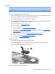
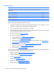
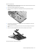
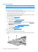
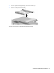
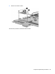
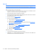
Table Of Contents
- Product description
- External component identification
- Illustrated parts catalog
- Removal and replacement procedures
- Preliminary replacement requirements
- Component replacement procedures
- Service tag
- Computer feet
- Battery
- SIM
- Bluetooth module
- Expansion memory module
- WLAN module
- Primary hard drive
- WWAN module
- Optical drive
- Switch cover and keyboard
- LED board
- RTC battery
- Secondary hard drive
- Primary memory module
- Display assembly
- Top cover
- Speaker
- System board
- ExpressCard assembly
- Modem module
- Fan
- Heat sink
- Computer Setup
- Specifications
- Computer specifications
- 12.1-inch, WXGA display specifications
- Hard drive specifications
- DVD-ROM Drive specifications
- DVD±RW and CD-RW SuperMulti Double-Layer Combo Drive specifications
- System DMA specifications
- System interrupt specifications
- System I/O address specifications
- System memory map specifications
- Screw listing
- Backup and recovery
- Connector pin assignments
- Power cord set requirements
- Recycling
- Index
Remove the system board:
1. Release the ZIF connector to which the front LED board cable is attached and disconnect the front
LED board cable (1) from the system board.
2. Disconnect the speaker cable (2) from the system board.
3. Remove the three Torx8 T8M2.5×6.0 screws (3) that secure the system board to the base
enclosure.
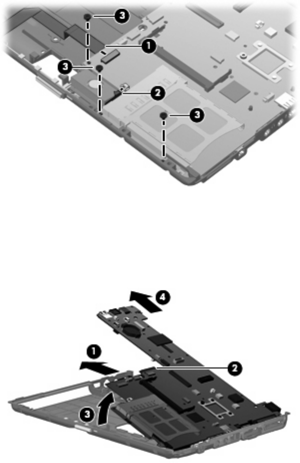
4. Flex the left side of the base enclosure (1) until the RJ-11 jack and USB ports are clear of the
openings in the base enclosure.
5. Use the optical drive connector (2) to lift the left side of the system board (3) until it rests at an
angle.
6. Remove the system board (4) from the base enclosure by sliding it up and to the left.
Reverse this procedure to install the system board.
Component replacement procedures 85