
Laptop User Manual
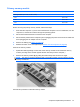
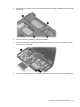
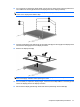
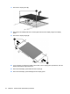
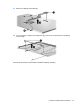
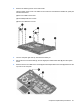
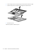
Table Of Contents
- Product description
- External component identification
- Illustrated parts catalog
- Removal and replacement procedures
- Preliminary replacement requirements
- Component replacement procedures
- Service tag
- Computer feet
- Battery
- SIM
- Bluetooth module
- Expansion memory module
- WLAN module
- Primary hard drive
- WWAN module
- Optical drive
- Switch cover and keyboard
- LED board
- RTC battery
- Secondary hard drive
- Primary memory module
- Display assembly
- Top cover
- Speaker
- System board
- ExpressCard assembly
- Modem module
- Fan
- Heat sink
- Computer Setup
- Specifications
- Computer specifications
- 12.1-inch, WXGA display specifications
- Hard drive specifications
- DVD-ROM Drive specifications
- DVD±RW and CD-RW SuperMulti Double-Layer Combo Drive specifications
- System DMA specifications
- System interrupt specifications
- System I/O address specifications
- System memory map specifications
- Screw listing
- Backup and recovery
- Connector pin assignments
- Power cord set requirements
- Recycling
- Index
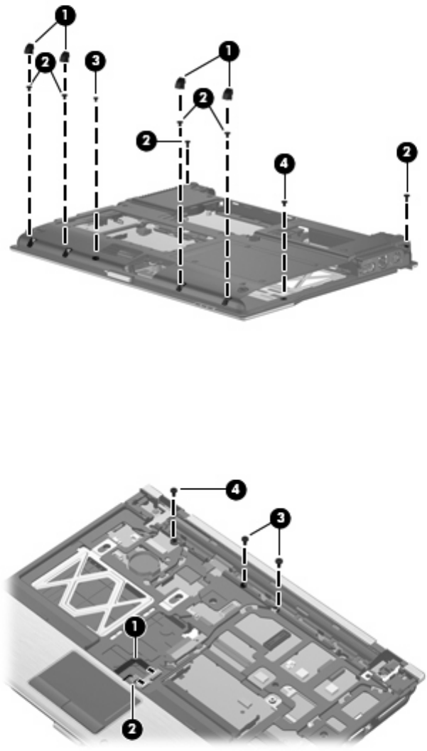
2. Remove the following screw covers and screws:
(1) Four rubber screw covers. The rubber screw covers are included in the Rubber Kit, spare part
number 481106-001.
(2) Six Torx T8M2.5×6.0 screws.
(3) One Phillips PM2.0×5.0 screw.
(4) One Torx T8M2.0×5.0 screw.
3. Turn the computer right-side up, with the front toward you.
4. Disconnect the TouchPad cable (1), and the fingerprint reader board cable (2) from the system
board.
5. Remove the two Torx T8M2.5×6.0 screws (3) and the Phillips PM2.0×6.0 screw (4) that secure the
top cover to the computer.
Component replacement procedures 81