
Laptop User Manual
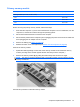
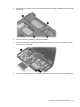
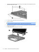
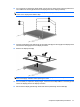
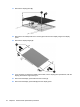
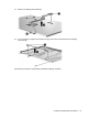
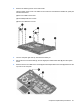
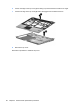
Table Of Contents
- Product description
- External component identification
- Illustrated parts catalog
- Removal and replacement procedures
- Preliminary replacement requirements
- Component replacement procedures
- Service tag
- Computer feet
- Battery
- SIM
- Bluetooth module
- Expansion memory module
- WLAN module
- Primary hard drive
- WWAN module
- Optical drive
- Switch cover and keyboard
- LED board
- RTC battery
- Secondary hard drive
- Primary memory module
- Display assembly
- Top cover
- Speaker
- System board
- ExpressCard assembly
- Modem module
- Fan
- Heat sink
- Computer Setup
- Specifications
- Computer specifications
- 12.1-inch, WXGA display specifications
- Hard drive specifications
- DVD-ROM Drive specifications
- DVD±RW and CD-RW SuperMulti Double-Layer Combo Drive specifications
- System DMA specifications
- System interrupt specifications
- System I/O address specifications
- System memory map specifications
- Screw listing
- Backup and recovery
- Connector pin assignments
- Power cord set requirements
- Recycling
- Index
12. If it is necessary to replace the display bezel, remove the four rubber screw covers (1) and the four
Torx T8M2.5×6.0 screws (2) that secure the display bezel to the display assembly.
NOTE: The rubber screw covers on the display bezel top edge are thicker than the rubber screw
covers on the display bezel bottom edge.
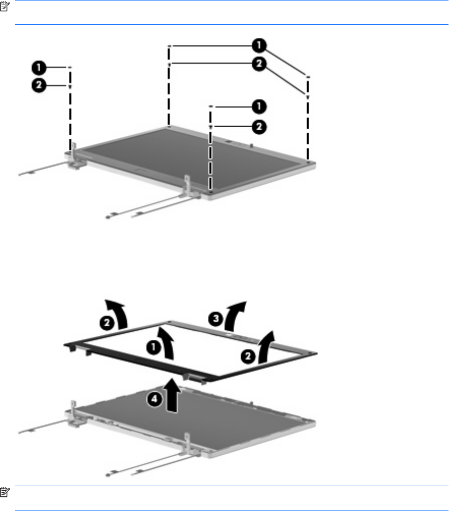
13. Flex the inside edges of the bottom (1), left and right sides (2), and the top (3) of the display bezel
until the bezel disengages from the display enclosure.
14. Remove the display bezel (4).
NOTE: Remove excess adhesive from the bezel and display enclosure when you remove the
bezel, and reapply adhesive before replacing the bezel.
15. If it is necessary to replace the display hinges, remove the two Phillips PM2.5×4.0 screws (1) that
secure the display panel to the display enclosure.
16. Disconnect the display passthrough board and camera passthrough board cables (2).
Component replacement procedures 77