
Laptop User Manual
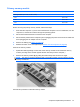
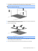
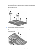
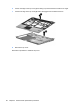
Table Of Contents
- Product description
- External component identification
- Illustrated parts catalog
- Removal and replacement procedures
- Preliminary replacement requirements
- Component replacement procedures
- Service tag
- Computer feet
- Battery
- SIM
- Bluetooth module
- Expansion memory module
- WLAN module
- Primary hard drive
- WWAN module
- Optical drive
- Switch cover and keyboard
- LED board
- RTC battery
- Secondary hard drive
- Primary memory module
- Display assembly
- Top cover
- Speaker
- System board
- ExpressCard assembly
- Modem module
- Fan
- Heat sink
- Computer Setup
- Specifications
- Computer specifications
- 12.1-inch, WXGA display specifications
- Hard drive specifications
- DVD-ROM Drive specifications
- DVD±RW and CD-RW SuperMulti Double-Layer Combo Drive specifications
- System DMA specifications
- System interrupt specifications
- System I/O address specifications
- System memory map specifications
- Screw listing
- Backup and recovery
- Connector pin assignments
- Power cord set requirements
- Recycling
- Index

Display assembly
Description Spare part number
12.1-inch, WXGA AntiGlare display assembly
With a webcam 492576-001
Without a webcam 492575-001
Display bezel (includes HP logo and computer model number label)
For use with models that include a webcam 495022-001
For use with models that do not include a webcam 495019-001
Display bezel adhesive 497013-001
Display Hinge Kit (includes left and right hinges and brackets) 481098-001
Display panel cable
For use with models that include a webcam 495023-001
For use with models that do not include a webcam 495021-001
Microphone 492573-001
Display enclosure (includes HP logo, wireless antenna transceivers and cables)
With webcam 496490-001
Without webcam 495020-001
Before removing the display assembly, follow these steps:
1. Shut down the computer. If you are unsure whether the computer is off or in Hibernation, turn the
computer on, and then shut it down through the operating system.
2. Disconnect all external devices connected to the computer.
3. Disconnect the power from the computer by first unplugging the power cord from the AC outlet and
then unplugging the AC adapter from the computer.
4. Remove the battery (see
Battery on page 46).
5. Remove the Bluetooth compartment cover (see
Bluetooth module on page 48).
6. Remove the memory module compartment cover (see
Expansion memory module on page 50).
7. Remove the hard drive bay cover (see
Primary hard drive on page 55).
8. Remove the broadband wireless compartment cover (see
WWAN module on page 58).
9. Remove the switch cover and keyboard (see
Switch cover and keyboard on page 62).
Remove the display assembly:
1. Close the computer and turn it upside down, with the rear panel toward you.
2. Disconnect the wireless antenna cables from the WLAN module (1), and feed them down through
the hole (2).
74 Chapter 4 Removal and replacement procedures