
Laptop User Manual
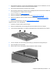
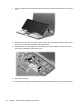
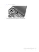
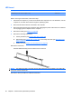
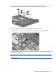
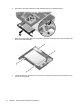
Table Of Contents
- Product description
- External component identification
- Illustrated parts catalog
- Removal and replacement procedures
- Preliminary replacement requirements
- Component replacement procedures
- Service tag
- Computer feet
- Battery
- SIM
- Bluetooth module
- Expansion memory module
- WLAN module
- Primary hard drive
- WWAN module
- Optical drive
- Switch cover and keyboard
- LED board
- RTC battery
- Secondary hard drive
- Primary memory module
- Display assembly
- Top cover
- Speaker
- System board
- ExpressCard assembly
- Modem module
- Fan
- Heat sink
- Computer Setup
- Specifications
- Computer specifications
- 12.1-inch, WXGA display specifications
- Hard drive specifications
- DVD-ROM Drive specifications
- DVD±RW and CD-RW SuperMulti Double-Layer Combo Drive specifications
- System DMA specifications
- System interrupt specifications
- System I/O address specifications
- System memory map specifications
- Screw listing
- Backup and recovery
- Connector pin assignments
- Power cord set requirements
- Recycling
- Index
1. Shut down the computer. If you are unsure whether the computer is off or in Hibernation, turn the
computer on, and then shut it down through the operating system.
2. Disconnect all external devices connected to the computer.
3. Disconnect the power from the computer by first unplugging the power cord from the AC outlet and
then unplugging the AC adapter from the computer.
4. Remove the battery (see
Battery on page 46).
5. Remove the WWAN module compartment cover (see
WWAN module on page 58).
6. Remove the expansion memory module compartment cover (see
Expansion memory module
on page 50).
7. Remove the hard drive bay cover (see
Primary hard drive on page 55).
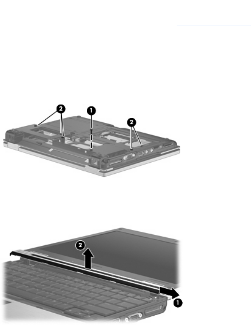
Release the switch cover and keyboard:
1. Position the computer with the bottom facing up.
2. Remove the Phillips BP2.5×6.0 screw (1) that secures the switch cover to the computer.
3. Loosen the five Phillips PM2.5×11.0 captive screws (2) that secure the keyboard to the computer.
4. Turn the computer over so that the top side is facing up, and the front is facing toward you.
5. Open the display as far as possible.
6. Slide the switch cover to the right (1), and lift to release the switch cover (2).
Component replacement procedures 63