
Laptop User Manual
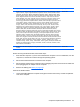
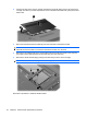
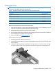
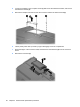
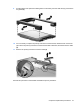
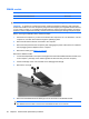
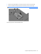
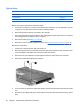
Table Of Contents
- Product description
- External component identification
- Illustrated parts catalog
- Removal and replacement procedures
- Preliminary replacement requirements
- Component replacement procedures
- Service tag
- Computer feet
- Battery
- SIM
- Bluetooth module
- Expansion memory module
- WLAN module
- Primary hard drive
- WWAN module
- Optical drive
- Switch cover and keyboard
- LED board
- RTC battery
- Secondary hard drive
- Primary memory module
- Display assembly
- Top cover
- Speaker
- System board
- ExpressCard assembly
- Modem module
- Fan
- Heat sink
- Computer Setup
- Specifications
- Computer specifications
- 12.1-inch, WXGA display specifications
- Hard drive specifications
- DVD-ROM Drive specifications
- DVD±RW and CD-RW SuperMulti Double-Layer Combo Drive specifications
- System DMA specifications
- System interrupt specifications
- System I/O address specifications
- System memory map specifications
- Screw listing
- Backup and recovery
- Connector pin assignments
- Power cord set requirements
- Recycling
- Index
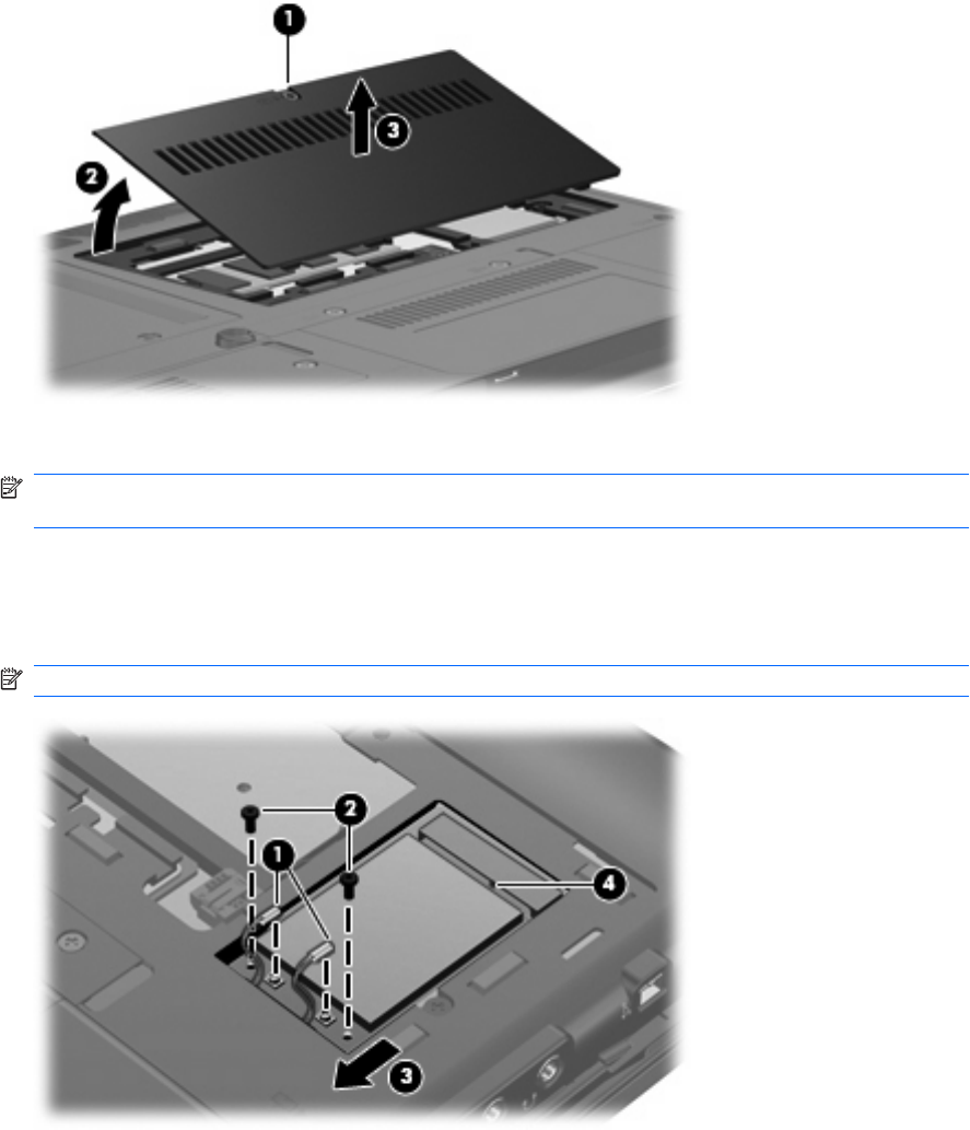
2. Lift the front edge of the memory module compartment cover (2), swing it back, and remove the
cover (3). The memory module compartment cover is included in the Plastics Kit, spare part number
492577-001.
3. Disconnect the WLAN antenna cables (1) from the terminals on the WLAN module.
NOTE: The black WLAN antenna cable is connected to the WLAN module “Main” terminal. The
white WLAN antenna cable is connected to the WLAN module “Aux” terminal.
4. Remove the two Phillips PM2.0×4.0 screws (2) that secure the WLAN module to the computer.
(The edge of the module opposite the slot rises away from the computer.)
5. Remove the WLAN module (3) by pulling the module away from the slot at an angle.
NOTE: WLAN modules are designed with a notch (4) to prevent incorrect insertion.
Reverse this procedure to install the WLAN module.
54 Chapter 4 Removal and replacement procedures