
Laptop User Manual
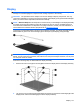
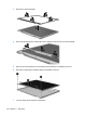
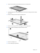
Table Of Contents
- Product description
- External component identification
- Illustrated parts catalog
- Removal and replacement procedures
- Preliminary replacement requirements
- Component replacement procedures
- Service tag
- Computer feet
- Battery
- SIM
- Bluetooth module
- Expansion memory module
- WLAN module
- Primary hard drive
- WWAN module
- Optical drive
- Switch cover and keyboard
- LED board
- RTC battery
- Secondary hard drive
- Primary memory module
- Display assembly
- Top cover
- Speaker
- System board
- ExpressCard assembly
- Modem module
- Fan
- Heat sink
- Computer Setup
- Specifications
- Computer specifications
- 12.1-inch, WXGA display specifications
- Hard drive specifications
- DVD-ROM Drive specifications
- DVD±RW and CD-RW SuperMulti Double-Layer Combo Drive specifications
- System DMA specifications
- System interrupt specifications
- System I/O address specifications
- System memory map specifications
- Screw listing
- Backup and recovery
- Connector pin assignments
- Power cord set requirements
- Recycling
- Index
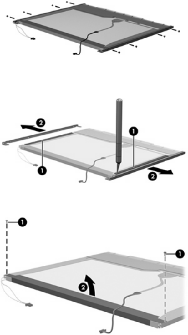
8. Remove all screws that secure the display panel frame to the display panel.
9. Use a sharp-edged tool to cut the tape (1) that secures the sides of the display panel to the display
panel frame.
10. Remove the display panel frame (2) from the display panel.
11. Remove the screws (1) that secure the backlight cover to the display panel.
12. Lift the top edge of the backlight cover (2) and swing it outward.
13. Remove the backlight cover.
14. Turn the display panel right-side up.
Display 149