
User guide
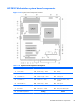
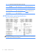
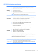
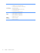
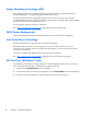

Table 1-20 System board component descriptions (continued)
10 Serial 24 Auxiliary fan 2 (rear) 39 Crisis recovery jumper
SAS/SATA 25 CPU/memory fans 40 ME/AMT Flash override
11 AHCI 6Gb/s 26 Front fan 1 (top) 41 Password jumper
12 Hard disk drive LED 27 Front fan 2 (bottom)
NOTE: For related expansion card
slot information, see
Expansion slots
on page 84.
13 SAS/SATA 6Gb/s 28 Liquid cooling 0 power
14 SAS (optional) 29 Liquid cooling 1 power
15 SCU 3Gb/s 30 Rear chassis fans
HP Z820 Workstation system board architecture
Figure 1-25 System board block diagram
NOTE: The PCIe designators indicate the mechanical connector size and number of electrical PCIe
lanes routed to an expansion slot. For example, x16(8) means that the expansion slot is mechanically a
x16 length connector, with 8 PCIe lanes supported.
34 Chapter 1 Hardware overview