
User guide
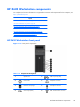
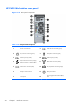
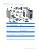
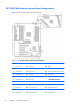
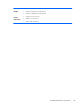
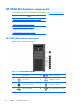

Table 1-16 System board components descriptions (continued)
12 Serial (optional) 23 CPU1 memory fan (optional) Service
24 Rear fans 35 Clear CMOS button
For related expansion card slot information, see
Expansion slots
on page 84
36 ME/AMT flash override
37 Password jumper
HP Z620 Workstation system board architecture
Figure 1-20 System board block diagram
NOTE: The PCIe designators indicate the mechanical connector size and number of electrical PCIe
lanes routed to an expansion slot. For example, x16 (8) means that the expansion slot is mechanically
a x16 length connector, with 8 PCIe lanes supported.
HP Z620 Workstation components
27